Exhibit 6: User’s Manual External Radio Frequency Power Amplifier ACOM 1500 Model 1500 Array Solutions 2611 North Beltline Rd Suite 109 Sunnyvale, Texas 75182 USA Tel: 214 954 7140 fax: 214 954 7142 E-mail: info@arraysolutions.
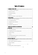
Table of Contents 1. GENERAL INFORMATION .................................................................... …3 1-1. Introduction and Description ................................................................ 3 1-2. Owner Assistance ................................................................................. 3 1-3. Equipment Supplied ............................................................................. 3 1-4. Features ..........................................................................
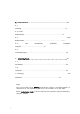
6. MAINTENANCE .................................................................................................... 17 6-1. Cleaning………………………………………………………………………………….17 6-2. Fuses Replacement………………………………………………………………………17 6-3. Tube Replacement……………………………………………………………………….17 6-4. The ACOM1500 Simplified Schematic Diagram…………………………………………17 6-5. Troubleshooting……………………………………………………………………..…..18 7. SPECIFICATIONS……………………………………………………………………..20 7-1. Parameters………………………………………………………………………………..20 7-2.
1. GENERAL INFORMATION 1-1. Introduction and Description This manual explains the installation, operation, and maintenance of the ACOM1500 HF+6 meters linear amplifier. The ACOM1500 is a complete and self-contained linear amplifier that covers all amateur bands from 1.8 through 54MHz and provides over 1500W PEP (1200W continuous carrier) output power with less than 85W exciter drive. Antenna VSWR up to 3:1 is acceptable at full power.
Using an EXCEL APPLICATION (available from ACOM or your dealer free of charge) and a PC you can decode the signatures by yourself, too. • Less noise in the shack: the input bypassing and the vacuum antenna relays are virtually silent even in QSK CW mode due to their special mounting. • Less QRM and improved Electro Magnetic Compatibility during tuning. Antenna matching can be achieved in less than 10 seconds at a quarter of nominal output power.
W A R N I N G notes call attention to a procedure which, if not correctly performed, could result in personal injury, fire hazard or electric shock. C A U T I O N notes call attention to a procedure which, if not correctly performed, could result in equipment damage, not only in the amplifier. N O T E notes call attention to a procedure which, if not correctly performed, could result in inconvenience.
2. INSTALLATION 2-1. Unpacking and Initial Inspection NOTE Before you start to install the amplifier, thoroughly read this manual. First, carefully inspect the cardboard carton and its contents for physical damage. If damage is noticed, notify your dealer immediately. Delay may infringe carrier's warranty conditions. Keep all packing for possible future transportation! 2-2.
No magnetic-field sensitive devices should be located next to the right side of the amplifier as its power transformer is located there. It's best to position it to the right of your transceiver. No temperature sensitive devices should be located above the exhaust hot air area, so don't push it under a shelf. You may prefer to use the bottom scales of both variable capacitor knobs (TUNE and LOAD) if you install it on a shelf.
c) Connect a suitable coaxial cable from your antennas to the appropriate amplifier output on the rear panel, marked ANTENNA 1, ANTENNA 2, and ANTENNA 3, using PL-259 plugs with PTFE insulation. d) Run a cable terminated in a Phono (RCA) connector from the transceiver socket providing "ground on transmit" control signal to the amplifier rear panel KEY-IN socket. NOTE Your amplifier will not work if KEY-IN is not connected properly.
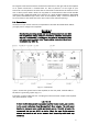
Make sure the main Power Switch on the rear panel is in OFF position and insert amplifier's mains plug into the wall outlet prepared for it. The amplifier remains switched off. 2-5. Installation of External Fan This fan (Fig. 2-1) is not necessary in SSB and CW modes, nor in continuous carrier modes (RTTY, SSTV etc.) with carrier down times of maximum 15 minutes and a subsequent pause of 3 minutes. For higher duties or increased ambient temperatures the fan is recommended.
Fig.3-1 ACOM1500 Display and Control You'll note that the upper line of the LCD always reads the peak forward power, even in STBY mode. The 1500W scale resolution is 15W per bar. Note that levels below 20W may be not detected. NOTE If the characters on the fluorescent dispaly are dim, please follow the method of Display brightness control described in S.5-1.
a) You can use the OFF LINE information screens and control functions. They refer to the auto-protection signatures list, Display brightness control, as well as the Auto-Operate feature. This is described in S5. b) You can turn on the amplifier and start the warm-up sequence. After 3 minutes you may tune and begin operating the amplifier and you can use the ON LINE information screens or control functions (see below). 4.
Pressing either the PREV or NEXT buttons during this period will result in changing the screen to one of the I4 available information screens described in S.4-5 below. This action will not influence the warming-up process, so you may pass through all information screens, for instance to monitor the High Voltage value or the Exhaust Air temperature. You can also return to the old one to see how many seconds are still needed for the tube's heater.
4-4. Tuning Tuning is possible only in operate mode, so you may need to press the OPER button in order to illuminate the LED above it (unless Auto-Operate is active). a) Preliminary information. Tuning the amplifier is a procedure of matching the impedance of the currently used antenna to the optimum tube load resistance. This will ensure maximum plate efficiency and RF gain at nominal output power, with minimum IMD at that.
We recommend that you tune-up at the center frequencies of the preferred frequency band. First select the band switch and the correct antenna number (never with RF applied!). Then use table 4-I in order to achieve an approximate preset for both TUNE capacitor and LOAD capacitor knobs: Band, MH z Tune Knob Dial Load Knob Dial 1.8 - 2 62 - 30 65 - 38 3.5 - 4 59 - 40 72 - 53 7 - 7.3 57 - 55 65 - 60 10.1 - 10.2 15 - 14 27 - 26 14 - 14.35 60 - 50 32 - 30 18 - 18.2 70 - 68 67 - 65 21 - 21.
NOTE Appearance of an arrow on either left or right TRI scale edges means that the LOAD knob is too far from the proper position. To correct this, turn the LOAD knob to the prompted direction until the triangle marker appears inside the scale field. I _____!_____ no marker: use TUNE knob for max. P to get any marker. IIII > ____!_____ marker is a far left: turn LOAD knob pointer to right until marker inside.
b) You can control the display brightness, Auto-Operate feature, and antenna outputs assignment also while ON LINE. In order to enter the control menu press the PREV+NEXT buttons simultaneously and hold them for two seconds. Further proceed as described for OFF LINE mode below - see S.5-1, S.5-2, and S.5-3 for details. 4-6.
5. OFF LINE MODE There are two control functions and I4 information screens available in this state of the amplifier. You can control the VFD brightness, enable/disable the Auto-Operate feature, and assign the antenna outputs. You can also list the auto - protection signatures. The tube is not powered at all (only the micro-controller is active) during these operations. 5-1. Display brightness control Press the PREV+NEXT buttons simultaneously and the “Brightness=…" screen will appear on the bottom line.
In order to read them press the OPER button while OFF LINE. The display will light at full brightness and you'll see the beginning of the signatures list. Use NEXT and PREV buttons to navigate through 7 pairs of screens. For each auto-protection trip there is a pair of information screens, beginning with nA... and nB... where: - "n" is the successive number of the event (nr.I is the latest, nr.7 is the oldest one); - A and B mark the first and the second part of an information screen pair.
6-4. The ACOM1500 Simplified Schematic Diagram • See Fig.6-I ACOM1500 Simplified Schematic Diagram. * The 4CX1000A/8168 ceramic and metal radial beam tetrode (V1) with plate dissipation of 1000W is grid-driven. It can dissipate up to 1000W when forced air cooled and is specifically designed for class AB1 RF linear amplifiers. The input signal from the RF INPUT jack is passed through a broadband input matching circuit, which comprises some components in the INPUT PCB and Rsw.
SB0 - tests made in Stand-By, during the warm-up period or while entering Stand By (from Operate); SB2 - tests made during Stand-By, after the warm-up period; PR0 - tests made while entering Operate; PR2 - tests made during Operate; TR0 - antenna relay tests made while changing from Tx to Rx (during Operate) TR2 - antenna relay tests made while changing from Rx to Tx (during Operate) TR4 - antenna relay tests made during Tx (Operate mode) TR6 - antenna relay tests made during Rx (Operate mode) c) The last
* Additional information is available from ACOM or from your dealer on how to interpret these values. Using an EXCEL APPLICATION (available from ACOM or your dealer free of charge) and a PC, you can decode these signatures by yourself. In case it is necessary to ship the amplifier please see S.7-3. 7. SPECIFICATIONS 7-1. Parameters a) Frequency Coverage: All amateur bands I.8-54MHz, extensions and/or changes on request. b) Power Output: I500W PEP or 1200W continuous carrier, no mode limit.
h) Primary Power: I00-264V (I00, II0,I20, 200, 2I0, 220, 230 & 240V nominal taps, +I0% -I5% tol.), 50-60Hz, single phase, 3500VA consumption at rated output. i) Complies with CE safety and electromagnetic compatibility requirements as well as FCC-regulations (I0 & I2m bands lock provided). l) Size & Weight (operating): W422mm x D355mm x HI95mm, 26.5kg. (I6.6 x I4 x 7.7 inches, 58.4 Lbs) m) Operating environments: - Temperature range: 0...+50 degs. Celsius; - Humidity: up to 95% @ +35 degs. Celsius.
i) Tube: a single 4CX1000A/8168 ceramic and metal radial beam tetrode with plate dissipation of 1000W (forced air cooled, grid-driven), specifically designed for class AB1 RF linear amplifiers. 7-3. Storage and Shipment C A U T I O N Should you need to transport the amplifier, use the original packing as described below. First, switch off the amplifier. Pull the mains plug out of the wall outlet. Disconnect all cables from the rear panel of the amplifier (remove the ground connection the last).