
User Manual
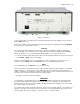
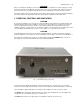
Exhibit 6 page 9 of 16
A minimum 30 seconds cathode warmup time is required but 60 seconds is recommended by the tube
producer. If you are not in a hurry, wait another 30 seconds after the green OPER LED has stopped
flashing.
4-2. Changing Operate and Standby Modes
The OPER button changes between two modes. When the green light above the button is illuminated, the
amplifier will remain ready to operate, even automatically returning from standby after a high-drive
protection trip. That is, after a protection trip, e.g., from an overdrive event, the amplifier will normally shift to
the STBY mode for several seconds, but it will automatically return to the OPER mode after that. This is the
Auto-Operate feature. Alternatively, the OPER button may be depressed manually to go to and remain in
the STBY mode, such as when you leave the station for a while. The green LED goes off and the Auto-
Operate function is suppressed temporarily. Pressing the OPER button again restores the Auto-Operate
feature.
4-3. RTTY Mode
Select the RTTY mode to operate continuous-duty modes such as RTTY, SSTV, or other data modes. The
LED indicator above the RTTY button illuminates and the amplifier operating parameters are changed to
reduce tubes dissipation. In the RTTY mode, the amplifier output power is reduced to a maximum of 500
W. There is no need to adjust tuning when changing between RTTY and normal modes.
CAUTION
To avoid damage not covered under warranty, do not change modes during transmission. That is, do not
change to or from RTTY or any other mode when transmitting.
4-4. Antenna change
By pressing the A1-A2 button, the amplifier output is switched between the two corresponding antenna
outputs, ANT1 and ANT2. The lights above the button indicate the current antenna selection.
CAUTION
To avoid damage (not covered under warranty) do not change the antenna during transmission.
4-5. Tuning
Tuning is possible only in the OPER mode.
a) Preliminary information.
Tuning the amplifier involves a procedure of matching the impedance of the antenna and transmission line
to the tubes characteristic load resistance. This will ensure maximum plate efficiency and RF gain at
nominal output power, with minimal distortion and spurious output. Note that REFLECTED POWER
readings depend on the antenna and transmission line impedances only, and not on amplifier tuning. If the
load impedance is not a nominally resistive 50-Ohms, the REFLECTED POWER reading will always show a
reading, no matter what the tuning settings. Proper tuning is always necessary, however, and will allow you
to operate at a high power level, without distortion or any danger to the amplifier. Note also that the real
OUTPUT POWER presented to the load (the antenna and transmission line) is equal to the difference
between the FORWARD and REFLECTED power readings. For instance, with a 2.5:1 VSWR, readings of
800 W and 150 W FORWARD POWER and REFLECTED POWER respectively, the real OUTPUT POWER
is 650 W. At very high VSWR levels, such as when no antenna is connected or a badly mismatched
antenna is used, the FORWARD and REFLECTED readings will be almost equal, while the real OUTPUT
POWER (the difference between them) will be nearly zero. The amplifier can operate safely as long as the
REFLECTED POWER is LESS THAN 250 W. Matching is assured for loads presenting a VSWR of up to
3:1. Nevertheless, for some loads and bands, matching is possible at even higher VSWR levels, but the
drive power must be reduced to prevent the REFLECTED POWER from exceeding 250W. Failure to comply
with these guidelines will cause the protection circuits to trip. For example, if the antenna VSWR were 5:1,
the maximum attainable forward power would be 540 W, 240 W of reflected power and real output to the
antenna and transmission line of only 300 W. In the event your antenna cannot be adjusted to produce a
lower VSWR, an external antenna tuner may be deployed.
CAUTION
At elevated VSWR levels, high voltages and high currents are distributed along the coaxial cable to the
antenna, risking internal arcing and heat generation, and likely damage to the cable and any antenna
switches that may be used. It is recommended that VSWR levels of more than 3:1 not be permitted with
coaxial cable above 14 MHz.