
User Manual
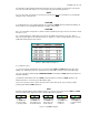
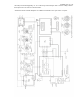
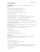
Exhibit 6 page 14 of 16
Fig.5-1 ACOM1011 Simplified Schematic Diagram
5-5. Service Functions
By pressing the OPER and RTTY buttons simultaneously, the upper LED bar-graph is switched to the
service mode, which is indicated by both red bar-graph lights and the yellow G1 light illuminating. Pressing
the OPER and RTTY buttons together again will select additional service measurement functions. Pressing
them a final time will return the amplifier to the normal operating mode. These steps are detailed below:
a) Press the OPER and RTTY buttons together. The two red lights on the right side of the upper bar-graph
will illuminate to confirm that the amplifier is in the service mode. The yellow G1 light will also illuminate.
The upper bar-graph should show a grid 1 current reading no higher than 5 mA (5 LEDs illuminated).
b) Pressing the OPER and RTTY buttons once again will now illuminate the yellow G2 light. This provides
an approximate reading of grid 2 voltage. The upper bar graph should show a voltage reading within the
range of either 270-330 Volts (9-11 LEDs illuminated) for RTTY or 210-360 Volts (7 to 12 LEDs illuminated)
for SSB and CW.
c) Pressing the OPER and RTTY buttons yet again will illuminate the yellow IP light. This provides an
approximate reading of combined plate current and grid 2 current. The reading should be no higher than
500 mA (10 LEDs illuminated) for RTTY or 550 mA (11 LEDs illuminated) for SSB and CW.
d) Pressing the OPER and RTTY buttons a final time will restore the upper bar-graph to its normal function
of indicating peak forward power.
NOTE
The auto-protection system will continue to operate in the service mode.