
User Manual
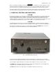
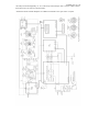

Exhibit 6 page 12 of 16
Do not open the amplifier. Cleaning the amplifier outer surface may be safely accomplished by using a
piece of soft cotton cloth lightly moistened with clean water.
5-2. Fuses Replacement
WARNING
If your amplifier is only fitted with one line (mains) fuse, it is suitable for the European Community ONLY.
Your dealer will check that your amplifier is correctly fused before it is shipped to you, based upon your
indicated location. Customers should check with a qualified electrician if the amplifier is to be used outside
the country in which it was purchased.
CAUTION
For 120 V ac operation, the fuses should be rated at 10 A; for 240 V ac operation, the fuses should be rated
at 6.3 A. If it is necessary to replace the line (mains) fuses, use only those that are permitted under local
safety codes.
The two primary line (mains) fuses in the amplifier are located on the rear panel (Fig. 2-1). They are of the
fast (quick blow) type, European size 5 x 20 mm. Use 10 A for 100-120 V ac operation; 6.3 A for 200-240 V
ac operation. Suitable types are:
For 120 V: 10 A 250 V 5 x 20 mm fast (quick blow), Littlefuse 0217010; Wickmann 1942100000
For 240 V: 6.3 A 250 V 5 x 20 mm fast (quick blow), Littlefuse 021706.3; Wickmann 1931630000
Besides the primary fuses, there are also fuses located on the HV PCB and on the MAINS PCB (inside the
amplifier). They are European size 5 x 20 mm, 0.8A, 2 A and 5 A, time lag (slow-blow) type.
Suitable types are:
HV PCB: 2 A 250 V SLOW BLOW (Time Lag) 5 x 20 mm; Littlefuse 0218002; Wickmann 1951200000
MAINS PCB: 5 A 250 V SLOW BLOW (Time Lag) 5 x 20 mm; Littlefuse 0218005; Wickmann 1951500000
MAINS PCB: 0.8 A 250 V SLOW BLOW (Time Lag) 5 x 20 mm; BUSSMANN type S504-800mA.
These latter fuses must not be replaced by the user. Replacing these internal fuses is potentially dangerous
and must be done only by a trained service technician. Contact your ACOM dealer for assistance.
5-3. Tubes Replacement
Two 4CX250B (7203) ceramic-metal tetrodes are used in the amplifier. The new tubes must be supplied as
a Matched Pair with close electrical characteristics. Replacement is a complex and potentially dangerous
operation that involves adjustment of the plate idling current. This should not be attempted by the user.
Contact your ACOM dealer.
5-4. Simplified Schematic Diagram
See Fig. 5-1 ACOM1011 Simplified* Schematic Diagram. The two 4CX250B (7203) ceramic-metal tetrodes
(V1 and V2) with a total plate dissipation of 500W (forced air cooling) are grid-driven. The input signal from
the RF INPUT jack is passed through a broadband input matching circuit, which consists of components on
the INPUT PCB and includes the drive-power swamping resistor Rsw. This circuit tunes out the input
capacitance of the tubes. The swamping resistor Rsw is a termination load for the matching circuit and can
dissipate up to 80 W of RF drive power. It also eliminates any tendency toward oscillation by the tubes,
ensuring excellent RF stability of the amplifier.
The cathode resistors Rc1 and Rc2 create DC and RF negative feedback, thus stabilizing gain and
equalizing frequency response. The combinations Lp1-Rp1 and Lp2-Rp2 in the plate circuits are VHF/UHF
parasitic suppressors. DC plate voltage is fed through chokes RFC1-RFC2 and the capacitor Cb3 blocks it
from the output. The output tank, comprised of LP1, LP2, LL, CP1-CP3, and CL1-CL4, forms a classic Pi-L
network and suppress harmonic frequency emissions. This circuit is switched and tuned by S1A-S1C and
the air variable capacitors CP1, 2 and CL1, 2. The output signal is fed through the antenna relays K1 and
K2 in the WATTMETER PCB. The WATTMETER PCB also includes a high-pass filter for frequencies below
100 kHz, and it prevents the plate supply from reaching the antenna.
The plate RF voltage is monitored through the capacitor Ca and together with the RF WATTMETER is the
main source of information for the control circuit of the amplifier in evaluating tuning quality. The control
circuit is based on the ATMEGA-8L micro-controller from Atmel. All voltages are delivered from the line
(mains) and HV PCBs. The currents of the control grids, screen grids, and the plates, as well as the