
User Manual

Page 9 of 34
connector of ACOM 600S. This will allow the amplifier to follow the changes of the frequency bands
automatically and without any transmission, while the operator is operating with the transceiver.
For control of the amplifier through the CAT/AUX interface you need a special cable between the transceiver
and CAT/AUX connector (type HD-15) on the rear panel of the amplifier – Fig. 2-1. Such a cable can be
supplied as an option along with the amplifier or you can buy it from your dealer additionally, but you can
assemble it yourself as well, using information from table 2-1 and your transceiver's manual.
Schematics of cables for connecting to many transceiver models are readily available in the Technical
compact disk (CD) – an option to the amplifier, as well as on the ACOM Internet page (S. 1-2).
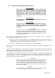
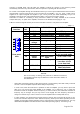
Table 2-1 shows the signals and the pin out of the CAT/AUX connector - rear panel of the amplifier.
Table 2-1
CAT/AUX
interface
PIN
NO.
PIN NAME
DESCRIPTION
SPECIFICATIONS
Rear panel
view
1
RxD
Received Data
TTL input
2
RxD
Received Data
RS232 input
3
TxD
Transmitted Data
RS232 output
4
TxD
Transmitted Data
TTL output
5
GND
Ground
0 Volt
6
BAND
voltage
Analogue input
0 to +8V
7
B. data 0
Bit 0
TTL input
8
B. data 1
Bit 1
TTL input
9
B. data 2
Bit 2
TTL input
10
B. data 3
Bit 3
TTL input
11
ON RMT
Remote Pwr On
+3 to + 6V / 5 to 20mA
1 to 2 seconds pulse
12
Debug
mode
CPU only Power
Input
+8 to + 12V / 0.4A
13
KEY-IN
Transmit Request
Rx/Tx control input
Less than +12.6V
Less than 6mA
14
KEY-OUT
Transmit Enable
O.C. output, 0 to +50V
20mA maximum
15
GND
Ground
0 Volt
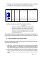
N O T E
Due to the variety of existing CAT protocols for different transceivers,
the amplifier response may be different for some transceiver models, as
described below.
- Some older transceivers employ a rather slow protocol or send frequency data with a delay of several
seconds – then the amplifier response will be delayed respectively;
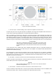
- In some cases, when the transceiver is powered on after the amplifier, you may need to press and
hold up for one second the button BAND of the amplifier, up or down (Fig. 3-2), to make the
transceiver inform the amplifier about its frequency; in other occasions, the transceiver transmits its
frequency only on changes and you may need to move slightly the main frequency dial knob or
change it in another way in order to announce it to the amplifier after an initial power turn on;
- in "split" operation, not all transceivers provide frequency data of VFO A and VFO B correctly; if your
receive and transmit frequencies fall in different frequency bands (Cross Band Operation) and the
amplifier unnecessarily switches between them at each transition receive/transmit (RX/TX), you may
deactivate the amplifier’s CAT/AUX interface control while operating "split" (S. 5-3 and Fig. 5-3).