
User Manual
Page 32 of 34
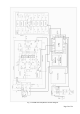
The Power Supply Unit (PSU) consists of two main assemblies:
- a rectifier and switching mode stage, not insulated from the mains; they provide a preliminary
regulation at 390V and power factor correction (PFC); the latter serves to minimize the mains-
frequency harmonics currents, ensuring a high power factor of the consumed current, and also limiting
the start-up mains current;
- mains-separated switching mode converter “390/50V” which supplies the power amplifier module with
+50V, insulated from the mains and regulated DC voltage; this is the main power supply of the
amplifier and it is protected against excessive consumption over 1200W; it is controllable ON and
OFF with a logic signal from the Control unit in the amplifier Operate and Stand-by modes
respectively.
In addition to the low-power and the main (+50V/1200W) power supplies, the PSU produces also three auxiliary
voltages:
- +13V DC voltage (non-insulated from the mains) for primary turning on and supporting the “PFC
control" assembly in the Power Supply unit;
- +5V DC voltage, insulated from the mains, for power supply of the Control unit, the low-power circuits
in the Power amplifier module, Filters, and Wattmeter units of the amplifier;
- +26V DC voltage, insulated from the mains - this is the operating voltage for the relays, fans, and
other low-power circuits in the amplifier.
Very efficient symmetrical L-C filters are placed at the input and output of the power supply unit. They suppress
the interferences in the radio frequency spectrum, providing perfect electromagnetic compatibility (EMC) with
both receivers and transmitters in the shack, exceeding the worldwide adopted standards. They also give the
power supply an extra resistance against external interferences propagating along the power network.
7-4. Using the fault codes (signatures) for diagnostics
In the nonvolatile memory of the Control unit there is room for data of the last 28 protection trips of the type
“serious fault” (HARD FAULT) – see S. 4-6(c). These are the values of all logic and analogous signals,
describing the regime and control of the amplifier, as well as the time when a problem has occurred (in worked
hours), and others.
The data can be downloaded through the built-in RS232 interface and stored in a computer plain-text format file
even when the amplifier cannot and should not be turned on after a serious fault – it is only needed to apply
external power to the Control unit in either way as described below (see also the FAULTS LOG menu – S. 5-5):
- through the connector for the CAT/AUX interface on the amplifier rear panel; without dismantling the
amplifier, on the “Debug mode” input (Table 2-1) a DC voltage between +8 and +15V towards ground
is applied. The consumed current is up to 0.4A in this mode;
- if the Control board has already been removed from the amplifier for another reason, it can be
powered directly with +5V and the faults log also downloaded via the RS232 interface, connecting the
board according to its own schematic diagram, shown in the Technical CD (option to the amplifier);
the consumption from +5V is the same: up to 0.4A.
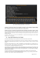
In the FAULTS LOG reading mode (Fig. 5-5), the Control board automatically begins to transmit the data from
its nonvolatile memory through the RS232 interface. Depending on the number of fault events stored in the
memory, the transmission may take between 0.5 and 12 seconds. A pause of 6 seconds follows the end of
data transmission which resumes again. The data is archived easily in a plain-text format through a computer
using a standard terminal emulating program (TTY).
You can send the recorded file to your dealer or to ACOM accordingly. They could also provide the necessary
instructions, if you choose to decode the downloaded hexadecimal data by yourself.