
User Manual
Page 29 of 34
C A U T I O N
The fuses must be rated for a current corresponding to your mains
nominal voltage: 10А for operation from 100-120VAC or 6.3А for
operation from 200-240VAC. Use only standard fuses!
C A U T I O N
Never replace any fuses inside the amplifier without special instructions
from your dealer! Blown internal fuses can be a symptom of a more
serious problem, which should be resolved beforehand. Unauthorized
replacement of inside fuses infringes the warranty conditions!
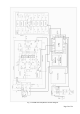
7-3. Simplified schematic diagram; theory of operation
a) Power Amplifier Module.
See Fig. 7-1 – ACOM 600S Simplified Schematic Diagram.
The "heart" of the power amplifier module comprises two pieces of dual N-channel field-effect (LDMOS)
transistors (Q101-Q101A and Q102-Q102A) type MRFE6VP6300H. The pair of transistors in each housing is
paralleled, and the two housings operate in a push-pull configuration with a common grounded source. In order
to provide minimum intermodulation distortions (IMD), the transistors operate in а linear AB class.
The manufacturer (Freescale Semiconductor) guaranties their endurance to mismatch with an arbitrary phase
and SWR up to 65:1. Besides this, each device is capable to dissipate 300W (total 600W) heat power in a
continuous carrier mode. These transistors have excellent temperature conductivity which allows the amplifier
to operate in continuous carrier mode with only 30% of their maximum allowed heat load. This guarantees the
high reliability of the amplifier.
The input signal enters connector J403 (RF INPUT), passes through the contacts of the input relay on the
Wattmeter board (turned in transmit – upwards the schematic diagram) and through connectors J405 and J101,
reaches the input attenuator ATT101 (10 dB). Besides reducing the input signal level to the gates, the
attenuator provides a significant improvement of the input SWR toward the transceiver.
From the attenuator output, the input signal is passed on to a balanced broadband matching circuit comprising
the transformer T101 and several R-L-C networks which compensate the input capacitance of the transistors
through the whole frequency range and provides two driving voltages for the transistors gates with equal
amplitude but 180º out of phase (in anti-phase).
The balanced choke/transformer T102 in the power supply, through its two main windings T102 and T102B
feeds DC supply voltage +50V from Power Supply Unit (connectors J103 and J104), to the drains of the
transistors Q101 and Q102 (the Power Supply Unit is described in (c) below).
The choke/transformer T102 contains yet one – third winding – T102A, which serves for creation of a local
negative feed back. Through the R-L-C networks R113-114, L105-106, and C115-116, it returns a small part of
the output voltage toward the gates of the transistors, but in anti-phase. It not only flattens the amplifier
frequency response through the operating frequency range, but also guarantees the amplifier parameters
irrespective of possible transistor tolerances.
The signal amplified by the transistors Q101 and Q102 is transferred from their drains through the matching
transformers T103–T103B, balun transformer T104, and connector J102, through connector J301 toward the
Filters unit input.
The Filters unit serves to provide the necessary harmonics and parasitic suppression in the output signal. It
allows the signal of the main operating frequency to pass to its output (connector J302) and at the same time
suppresses the signals with second and all higher harmonic frequencies (which are normally generated by the
final transistors). For covering the whole operating frequency range, the Filters unit includes eight separate low-
pass filters, one of which is selected by switching of several relays, controlled by the Control unit (described in
(b) below) depending on the current operating frequency band.
For a correct selection of the necessary filter, a small part of the input signal is diverted through connectors
J405 – J504 to be fed to the Control unit frequency counter input. According to the measured frequency or the
commands coming through the CAT/AUX or the RS232 interfaces, the Control unit selects the necessary filter
through the relay-coils control signals fed via connectors J503-J303.