
User Manual

Page 17 of 34
- thread ferrite beads with medium permeability (800-4000) over the power cord, the feeder and the
signal cables leading to the affected devices (TV etc); there are suitable “split” ferrites on the market
for this purpose with different sizes, shapes and parameters, inserted in locking plastic shells, which
do not need to be threaded through the cable and are simply put and locked over it; besides the size,
consider the frequency range in which the offered ferrites are effective – normally they are optimized
for suppression of interferences on HF (with larger permeability), with medium permeability for HF-
VHF or with low permeability - only the VHF range. The latter are ineffective for HF;
- whenever possible use shielded cables and ground their shields at both ends;
- shield (at least partly) the disturbed apparatus, for example, put under the keyboard, the desk
microphone or the Morse keyer a large metal sheet, connected to the grounding system of the shack;
- the addition of even quite simple low pass L/C or R/C filters directly to the disturbed inputs or outputs
of the apparatus is very effective, provided it is practically applicable.
Last but not least, have in mind that the benefit of the above measures is two-fold. Firstly - they reduce the
interferences from your transmissions to the ambient environment and secondly - they reduce the background
noise floor for your reception.
Practically, with no great efforts, implementing the above measures, you can reduce the background noise floor
with one or more S-units across the different bands. This will allow you not to miss weaker stations, which will
hear you because of your increased transmission power.
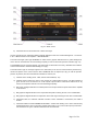
4. OPERATION WITH THE AMPLIFIER
4-1. Change of modes RX / TX and Operate / Stand-by; option AUTO OPERATE
a) In Stand-by mode, as well as with un-powered amplifier, receiving and transmitting with the
transceiver is implemented via RF by-pass between RF INPUT and RF OUTPUT of the amplifier.
At transmission in Stand-by, RF power of the transceiver is not amplified by the amplifier, the
control KEY-IN input does not influence over its operation, and the KEY-OUT output (S. 2-3(c))
follows the state of the KEY-IN input unconditionally.
b) In Operate mode the final stage of the amplifier is powered and it is fully functioning; the receive-
transmit (RX / TX) direction is controlled by the KEY-IN input:
- at open KEY-IN (Operate/RX mode), the transceiver receives the signals from the antenna through
the same RF by-pass path between RF INPUT and RF OUTPUT through which receiving is done with
amplifier turned off or in Stand-by mode;
- at grounded KEY-IN ((Operate/TX mode) the amplifier input relay connects the RF INPUT connector
(drive from the transceiver) toward the final stage input and the output relay feeds the amplified signal
to the antenna through the RF OUTPUT connector.
C A U T I O N
In order to provide time for the relays and the final stage in the amplifier
to switch safely from receive to transmit, the transceiver should provide
a dead time i.e. must “notify” the amplifier in due time grounding its
control KEY-IN input not later than 10ms before feeding drive power
toward the amplifier RF input. Otherwise, the “HOT SWITCHING
ATTEMPT” protection will trip.
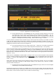
In Operate mode the KEY-OUT output (S. 2-3(c)) follows the state of the KEY-IN input only after all conditions
for safe transmission have been satisfied and found OK by the amplifier control unit. The KEY-OUT output duly
disables transmission, if this is inadmissible or there is a potential risk for the amplifier or the transceiver.
The two modes - Operate and Stand-by - may alternatively be changed in three different, independent ways
as described below: