
User Manual

Page 15 of 34
d) Check-up of the RX/TX commutation and the idling current without RF power.
Put the transceiver in such a regime that at pressed PTT or TX button a transmit request is applied to the
amplifier but with no RF power on the transceiver output. For example, select SSB mode with microphone
gain reduced to zero or CW mode with Morse key up to avoid any RF power while requesting transmit mode to
the amplifier by PTT or TX button (do not use automatic CW keyer or VOX).
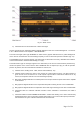
At pressing the PTT or the TX button without RF drive at the amplifier input, the green label “TX” on the basic
screen must become red “TX”. Note that the indicator reflects the TX request and not its working out. Besides
this, on indicator PA DC CURRENT must appear the final-stage idling current of around 1.0 – 1.4A, but neither
forward, nor reflected power must appear at the output.
If at pressing the PTT or the TX button and without RF drive at the amplifier input any indication of RF power at
the output still appears, it might be due to self-oscillation or it may be externally induced by co-sited powerful
transmitters. If you suspect self oscillation, check-up the coaxial cables to the input and output of the amplifier,
in particular the contact of their shields to the coaxial connectors (S. 2-3(d),(e)). To check for externally induced
RF power (especially if the reflected power is higher than the forward power) connect the antenna to a dummy
load via an external RF wattmeter - it should read zero RF power.
e) Test transmission.
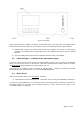
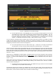
In the basic screen (Fig. 3-2) check-up whether the currently selected frequency band of the amplifier and the
transceiver frequency match the antenna band. If needed (when the CAT/AUX interface between the amplifier
and the transceiver is not connected), use BAND buttons (up and down) of the amplifier to switch to the desired
frequency band manually.
In order to continue with the test transmission, prepare the transceiver regime in the same way as it was done
in item (a) above: with continuous carrier and minimum power. Now in the Operate / RX mode select a
frequency which is presently not occupied and press the actuator for transmit (PTT) briefly, while watching the
following indicators of the amplifier:
- RX mode must be changed to TX;
- the reflected power must be below 20W;
- the forward power must be between 20 and 150W with minimum drive power from the transceiver
(between 1 and 5W expected with the power control set at minimum);
- PA DC VOLTAGE must be within 48-52V;
- PA DC CURRENT must be between 1 and 8A (depending on the transceiver power with its power
control set at minimum).
If the above test goes normally, push briefly the transmit actuator (PTT) once again, this time watching the
transceiver SWR indicator (i.e. the input SWR of the amplifier) – it must be below 1.2:1.
f) Setting of drive level and typical regime.
After the successful passing of checks up (a) to (e), in the same regime with continuous carrier and minimum
power, press the transmit actuator (PTT) for several seconds, observing the forward and reflected power at the
output, as well as the direct current consumed by the final stage – PA DC CURRENT. Increase the drive power
gradually – from minimum until the forward power at the amplifier output reaches 600W. Observe at the same
time that none of the indicators of the amplifier or the transceiver enters the colored alarm areas.
Reaching 600W forward power, check-up the following parameters (continuous carrier regime):
- the reflected power must not exceed 70W (for SWR 2:1) or better still to be below 25W (for SWR
1.5:1);
- PA DC CURRENT must be between 20 and 26A; it is normal that the current varies within these limits
at changing of the operating frequency and the antenna impedance;
- PA DC VOLTAGE must be within 48 – 52V;