
User Manual

Page 14 of 34
SWR are too high (over 5W or SWR over 2:1) immediately release the actuator and search for the reason as
follows:
- check-up again whether the output control is set at minimum;
- check-up whether the frequency on which you transmit is within the operating range of the selected
antenna;
- check-up the good working order of the connecting coaxial cables, connectors, and feed lines from
the transceiver antenna jack through the amplifier, the antenna switch or external tuner (if there is
such) to the BALUN transformer, and the antenna itself (S. 2-3(e)).
In case of difficulty use antenna measurement instruments or contact your dealer.
If the power and SWR are as expected, then go transmitting again and while watching the power and the SWR
indicators, increase transceiver power gradually from minimum to maximum (but not more than 200W, in order
not to overload the RF by-pass circuit of the amplifier).
If SWR remains below 2:1 (preferably below 1.5:1) at the last test, decrease the power from the transceiver to
minimum again and continue with the next check-up. Otherwise you will have to make corrections on the
antenna and / or feed-line matching or use an external tuner for this antenna. The tuner should handle the
maximum output power of the amplifier (S. 8-1(b)) at the respective antenna SWR.
b) Check-up in Stand-by mode.
After a successful check-up with non-powered amplifier, item (a), turn on its mains supply and run it to the basic
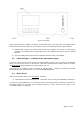
screen, as described in Sections 3-1 to 3-4 (Fig. 3-2).
For this check-up it is necessary that the amplifier is in the Stand-by mode. If the AUTO OPER option has been
activated at any previous switching on of the amplifier, it will automatically start in the AUTO OPER mode (Fig.
3-2 and S. 5-4) immediately after turning power on. In such a case, press once the OPR/STB button to return
the amplifier manually to the Stand-by mode.
In this state repeat the receive and transmit tests with the transceiver through the amplifier RF by-pass path, as
it was described in the preceding item (a). During these tests note also whether the bar-graphs and digital
indicators for forward and reflected power in the basic screen (S. 3.4(e),(f)) show respective RF power
presence. If the reflected power exceeds the forward power, verify that you have not interchanged involuntarily
the input and output coaxial cables to the amplifier (S. 2-3(d),(e)).
N O T E
The power indication is optimized around the 600W level and normally it is
unreliable below 50W.
c) Entering Operate mode.
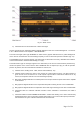
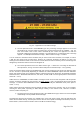
After a successful check-up in Stand-by mode, item (b), while you are in the basic screen, press the MENU
button. From the list select menu AMP MEASURE (Fig. 5-1). In the left-side of the screen select PA DC
VOLTAGE and in the right-side – PA DC CURRENT (use the ITEM1 or ITEM2 buttons to scroll the list if
needed). Press twice the rightmost EXIT button to return to the basic screen. The two selected parameters –
PA DC VOLTAGE and PA DC CURRENT - will be indicated in the basic screen as well – S. 3-4(b). In Stand-by
mode they must be zero.
Now press the OPR/STB button to put manually the amplifier in Operate mode (S. 3-2 and Fig. 3-2). The
OPER or the AUTO OPER indicator must flash and the indicator RX/TX must remain in condition RX. Besides
this, PA DC VOLTAGE must become 48-52V while PA DC CURRENT must remain zero.
At entering the Operate mode the receiving of the transceiver should not suffer. If it worsens and together with
this the indicator RX changes into TX and any current appears on the drain (PA DC CURRENT) although the
transceiver is in the receive mode, check if they normalize at return to the Stand-by mode.
If the problem occurs only at transition into the Operate mode and disappears at return to Stand-by, check the
control cable connected to the KEY-IN input – S. 2-3(b) – it is possible that the conductor is shortened to the
shield (ground) or the connection to the transceiver is wrong, thus wrongly requesting transmit mode toward the
amplifier during transceiver reception.