
User Manual

Page 13 of 34
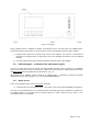
3-5. Control system – buttons and menus
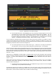
a) The OPR/STB and the BAND buttons are used for manual (local) control of the amplifier in the basic
screen (Fig. 3-2):
- the left-most button – OPR/STB is for alternative switching of the amplifier mode between Operate
and Stand-by;
- the next two buttons – BAND up and down arrows – serve for manual change of the frequency bands
in ascending or descending order; pressing and holding on either up or down arrow for one second
will refresh the information about the operating frequency on the CAT/AUX INTERFACE;
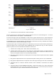
b) The right-most button – MENU (Fig. 3-2) – serves for access to the list of menus.
All necessary instruments, as well as the control and service options of the amplifier are structured in six
menus. Each of them has only one hierarchical level (menu depth) – Section 5 and Fig. 5. This simplified
menu structure gives the operator maximum clarity and possibility of easy navigation in them. More handiness
is provided by the uniform approach to the different menus:
- in each screen (the menu list and all tools in them) the left-most button is always HELP and the right-
most – always EXIT;
- the HELP button can be used at any time for obtaining of auxiliary information concerning the
currently activated screen (context sensitive help);
- the currently chosen menu title (for example AMP MEASURE) is always present at the top of the
menu;
- the EXIT button can be used at any time to leave the currently used menu or the menu list for possibly
easiest and fastest “return” to the basic screen (Fig. 3-2).
For more details of the control system and use of the menus see Section 5. MENUS – USEFUL OPTIONS.
3-6. Test transmission
To make sure that you have installed the amplifier correctly, before you put it in operation, make a test
transmission as described below. Repeat these tests for each new band and antenna, as well as after
installing a new or repaired antenna, antenna switch, tuner, and / or the connecting cables.
a) Check-up of RF by-pass path at non-driven amplifier.
For this check the amplifier must be completely installed and connected according to Section 2, but not
powered by the mains, i.e. the mains power plug must be pulled out from the mains outlet or the POWER ON
switch on the rear panel must be in turned off position. In any case the LED above ON/OFF button must be
dark for this test.
First, check if the transceiver reception is normal. If you observe a significant worsening of reception, search
for the problem first in the coaxial connections to the amplifier (S. 2-3(d),(e)).
If reception is normal, prepare the transceiver regime as follows:
- select a continuous carrier mode (CW, RTTY, FM or some digital mode);
- switch the microphone off (decrease its volume), ban the FSK respectively;
- reduce the output power to a minimum;
- select a suitable indication so that you can watch the transceiver output power and output SWR;
- if the transceiver has an antenna tuner – switch it off.
Now in receive mode select a frequency which is not occupied at the moment and press shortly the transmit
actuator (the PTT or the TX button) while observing the output power and the SWR indicators. If the power or