
User Manual

Page 12 of 34
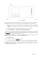
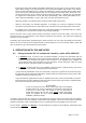
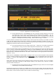
Fig. 3-2 Basic screen
b) Information area for measurements or alarm messages.
Any two operator-chosen parameters will be normally displayed in this area on black background – see the list
in S. 5-1 Measurements in the amplifier – AMP MEASURE.
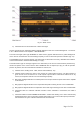
The alarm messages (either type WARNING or SOFT FAULT) appear with black font on yellow background
on the area for measurements and are flashing frequently in order to attract the operator's attention (Fig. 4-1).
The WARNING type of messages appear only temporarily (for about three seconds), afterwards the indication
of the measurements is restored automatically (S. 4-6(a)).
The SOFT FAULT type of messages appear in the same field (on the area for measurements) however they
remain and persist on the screen until the AUTO OPERATE time is elapsed (S.4-1(c)) or until the operator
presses any button, then the measurements indication is restored, too.
c) Indicator for the working mode - OPR, STB or AUTO OPER (S. 4-1).
d) Indicator RX/TX reflects the state of the request for transmit (KEY-IN input). The RX indication is
green and the TX is red. When a TX or RX request is present but it could not be worked out for any
reason, the respective indicator TX or RX is flashing frequently.
e) Bar-graph and digital indicator for forward power at the output. Reads the power fed from the amplifier
to the antenna.
f) Bar-graph and digital indicator for the output reflected power. Entering the red zone is inadmissible.
g) Bar-graph and digital indicator for temperature of the final stage. Entering the red area is inadmissible.
h) Information label for activated CAT/AUX interface. When CAT/AUX is deactivated, this label is
shaded.
i) Information label for activated REMOTE CONTROL – flashes after feeding one or more commands by
the RS232 interface. Dies out (remains shaded) after feeding one or more manual (local) commands
from the buttons or by the CAT/AUX interface from the transceiver.