
User Manual

Page 10 of 34
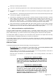
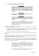
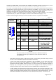
b) RS232 Interface. Table 2-2 shows signals and pin out of the RS232 connector on the rear panel of
the amplifier. Details about connecting and using the RS232 interface are given in the Technical
compact disk (CD) – option to the amplifier and / or in the respective control programs.
This connector can remain unconnected until you decide to use the amplifier with remote control.
Table 2-2
RS 232
interface
PIN
NO.
PIN
NAME
DESCRIPTION
SPECIFICATIONS
Rear panel
view
1
-
Not connected
-
2
TxD
Transmitted Data
RS232 level output
3
RxD
Received Data
RS232 level input
4
-
Not connected
-
5
GND
Ground
0 Volt
6
DSR
Data Set Ready
RS232 level input
7
-
Not connected
-
8
CTS
Clear To Send
RS232 level input
9
-
Not connected
-
3. INITIAL POWER ON AND SETTING INTO OPERATION
C A U T I O N
Do not turn on the amplifier for at least two hours after it is unpacked
and installed in its operating position. Pay particular attention whenever
the amplifier is moved from a very cold place to a very warm one
because unseen condensation may develop and this could result in
damage to the high voltage circuits of the amplifier. Under these
circumstanves, do not turn on the amplifier for at least 4 hours. A similar
effect could occur following a rapid warming of the room, such as winter
use of a powerful electric heater.
After having mounted and connected the amplifier according to the instructions in Section 2 INSTALLATION
and have followed all requirements, check whether mains switch on the rear panel is in turned-off position – in
Fig. 2-1 the rocker of the POWER ON switch must be protruding from the side of the “ON” inscription.
Afterwards insert the mains plug of the amplifier into the mains outlet prepared for it. For now the amplifier
remains turned off.
3-1. Low-energy (waiting) mode of the power supply
Now you can put the mains switch on the rear panel in a turned-on position, pushing its rocker so that it sinks
from the side of the “ON” inscription (Fig. 2-1). This will activate only the low-energy (waiting) mode of the
power supply and will illuminate the red LED above button ON/OFF on the front panel, while the main power
supply is still inactive and the display is dark.
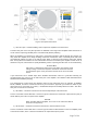
3-2. Front panel - controls and indication
a) ON/OFF button – serves for manual (local) start up of the power supply from low-energy (waiting)
mode of the power supply (S. 3-1) into working mode, i.e. for activating of the main power supply and
starting operation with the amplifier. The same button is used also for main power supply deactivation
– return into the low-energy (waiting) mode of the power supply at ceasing operation with amplifier.
b) LED indicator above the ON/FF button. Glowing only of the red LED indicator above the ON/OFF
button at a dark display shows that mains voltage is fed to the plug, the POWER ON switch on the
rear panel (Fig 2-1) is in a turned-on position, but the power supply is in its low-energy (waiting)
mode (S. 3-1). In this mode activation of the main power supply is expected to start operation with the
amplifier.