999-00451 Connected Door Lock Installation Instructions Secure Control from Anywhere™
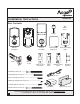
Installation Instructions 999-00451 Box Contents Screw Cover Key (2) Exterior Assembly Gasket Drive-in Collar Latch Interior Assembly Square Corner Face Plate Rechargeable Battery (2) Strike Plate Interior Mounting Plate Reinforcement Plate Dust Box (Optional) Mounting Screws (2) --------Mounting Plate Screw (1) ------------------ USB Cable Interior Housing Screw (1) ------------------------Battery Compartment Screws (2) ---------------------Latch & Strike Screws (4) ------------------------
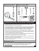
Tools you will need: Tools you may need: IMPORTANT INSTALLATION NOTES. PLEASE READ: • Remove the battery from the battery compartment and charge it in the Charging Cradle until the LED turns green. • The Array By Hampton™ connected door lock has a built-in solar panel that will charge the battery if positioned in direct sunlight. If unable to position the connected door lock in direct sunlight, you may need to charge the battery more frequently. You will see the battery status on the app.
Installation Overview Part Description A Key B Exterior Assembly C Cylinder D Tailpiece E Power Cable BATTERY COVER (L) RECHARGEABLE BATTERY (J) F Gasket G Latch H Interior Mounting Plate I Interior Assembly J Rechargeable Battery K Antenna Cover L Battery Cover M Tailpiece Receiver N Strike Plate O Reinforcement Plate P Dust Box Q Screw Cover BATTERY COMPARTMENT SCREWS (DD) INTERIOR ASSEMBLY (I) ANTENNA COVER (K) MOUNTING PLATE SCREW (BB) SCREW COVER (Q) INTERIOR HO
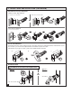
Pre-Installation Instructions 1. Charge Battery a. Remove the Battery Cover (L), Rechargeable Battery (J), Battery Charging Cradle, USB Cable and Wall Adapter. Remove the plastic tab on the Battery (J). Slide the Battery (J) into the Charging Cradle from the side. Charge the Battery (J) until the LED Light turns from red to green. b. Carefully remove the Antenna Cover (K) by gently pulling the edges outward slightly and lifting. b. Rechargeable Battery (J) Pull edge slightly outward a.
4. Install Latch and Strike Plate (Continued) Determine the Proper Faceplate Mortise on door edge chiseled: a. Square corner faceplate b. Round corner faceplate a b OR Door edge not chiseled: c. Drive-in collar option c Drive-in collar Set the Latch Backset The distance from the center of the bore hole to the edge of the door is called the backset. If the backset of your door is 2-3/8", you don’t need to adjust the latch. The backset is preset for 2-3/8".
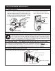
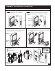
Deadbolt Installation Instructions 5. Install Lock Assemblies A. Door Bore Hole Options Option 1 Option 2 For door with bore hole 2-1/8" diameter proceed to STEP D. For door with bore hole 1-1/2" diameter follow Steps B and C for Mounting Plate Screw (BB) and Mounting Plate removal. Bore Hole 2-1/8" diameter Bore Hole 1-1/2" diameter A. A. OR Mounting Plate Screw (BB) Mounting Plate B.
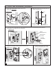
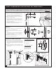
5. Install Lock Assemblies (Continued) E. Power Cable (E) goes underneath the latch. Insert Tailpiece (D) horizontally. F. Bulged part of the Interior Mounting Plate (H) must be toward the door. EXTERIOR VIEW Door Power Cable (E) E. F. Tailpiece (C) Tailpiece (D) Power Cable (E) Exterior Assembly (B) Exterior Assembly (B) Interior Mounting Plate (H) G. Feed Power Cable (E) through Interior Mounting Plate (H) as shown.
5. Install Lock Assemblies (Continued) J. Align the Tailpiece Receiver (M) of the Interior Assembly (I) onto the Tailpiece (D). Interior Assembly (I) Interior Assembly (I) INTERIOR VIEW Power Cable (E) Tailpiece Receiver (M) Tailpiece (D) J. J. K. Insert the two Battery Compartment Screws (DD) and tighten. Insert the Interior Housing Screw (CC) and tighten. Battery Compartment Screws (DD) CAUTION: Take care not to damage the antenna when inserting the Battery Compartment Screws (DD). K.
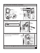
Door Preparation Instructions for New Doors If installing the Array By Hampton™ connected door lock on a new door, follow the door preparation instructions and use the template on Page 10. Mark Door with Template b a a. Mark the centerline for the deadbolt about 44" (1120 mm) from the floor, or about 5-1/2" (140 mm) above the center of an existing knob or lever. b. Apply the template to the door with the dotted fold line on the door edge. c.
TEMPLATE 3" Fold on dotted line and fit on door edge 1-9/16" 40mm 1-3/8" 35mm CL CL CL Make a 1" (25.4mm) hole at center of door edge 1-3/4" 45mm This line should be 3 inches. Measure it before using this template. If the line is not 3 inches when measured, print this instruction out, full scale on paper that is 8.5" x 11" and measure again.
ARRAY BY HAMPTON™ BATTERY MANUFACTURER’S INSTRUCTIONS WARNING: • Misusing the battery may cause it to get hot, explode, or ignite and cause injury. Follow the safety rules listed below: o Do not place battery in fire or heat the battery. o Do not penetrate the battery with nails, strike the battery with a hammer, step on the battery, or otherwise subject it to strong impacts or shocks. o Do Not Open, Crush, Heat Above 60°C (140°F), or Incinerate. • o Do not solder directly onto the battery.