
Manual


I PA.TNoI .tt9..o96I DATE12196 I SUPERSEDESI ,rig.DO9.I PAGE,O.tO
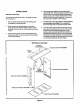
It an installation is madein which it is more desirable to mount the filter exterior to the unit, in the return duct work, or
olherwise, either the permanent filter supplied or a disposable filter may be used. If a disposable filter is used, the
minimum area required is as follows:
MOOELNO. FILTERAREA(MtN.)
PWC 182 480 sq. in.
PWC242 480 sq. in.
PWC302 480 sq. in.
THERMOSTAT
The room thermostatshouldbe locatedonan insidewall whereitwilt not besubjecttodrafts, sun exposureor heat
from electricalfixturesorappliances.Followthemanufacturer'sinstructionsenclosedwiththe thermostatforgeneral
installationprocedures.Colorcodedinsulatedwires(#18 AWG)shouldbe usedto connectthethermostattothe unit.
POWERAND CONTROLWIRING
ELECTRICALCONNECTIONS
ALLWIRINGSHOULDBEDONEIN ACCORDANCEWITH NATIONALELECTRICALCODE,ANSI/NFPA NO.70 (LATEST
EDITION).IN CANADA(_SAC22.2 Part 1 (LATESTEDITION),OR WITH LOCAL CODES,WHERETHEY PREVAIL.
NOTE: UNITSAREFACTORYWIREDFORA 230 VOLTPOWERSUPPLY. IF POWERSUPPLYIS 208 VOLTS. IT WILL
BENECESSARYTO CHANGEAWIRE CONNECTIONON UNIT TRANSFORMERFROM240V TERMINALTO20SV TER-
MINALAS SHOWNONWIRING DIAGRAM.
Usewiringwitha temperaturelimitationof 75°C rain. Runthe 208 or 230 volt, 60 hertzelectricpowersupplythrough
a fuseddisconnectswitchto thecontrolboxof the unitandconnectas showninthewiringdiagramlocatedon the in-
sideof the controlaccesspanel.
The unitmustbe electricallygroundedin accordancewith local codesor in the absenceof local codeswith the Na-
tionalElectricCodeANSI/NFPA No. 70 (latest edition)or CSAC22.2 Part 1 (latest edition).
Power supplyto the unit must be N.E.C. Class 1, and must complywith all applicablecodes. A fused disconnect
switchshouldbe field providedfor the unit. The switchmust be separatefromall othercircuits.If anyof the wire
suppliedwith the unit must be replaced, replacementwire mustbe of the type shownon the wiring diagram.
Electricalwiringmust besized tominimumcircuitampacitymarkedon the unit. USECOPPERCONDUCTORSONLYI
Eachunit must bewired with a separatebranchcircuitand be properlyfused.
SEQUENCEOFUNIT OPERATION
COOLING- WhenthethermostatisIn the coo[ingmode,the Ocircuitis poweredwhichenergizesthereversing valve.
Uponcoolingdemand,the thermostatclosescircuitR toYand G. ClosingRtoY closestheunitcontactor,startingthe
compressorandoutdoorfan. ThethermostatautomaticallyclosesRtoGcircuitwhichalsobringsonthe indoorblower
at thesametime. Uponsatisfyingcoolingdemand,thethermostatwillopentheabovecircuitsandopenthemaincon-
tactor,stoppingthe compressorand outdoorfan. If theunitis equippedwith a time delay,the blowerwill continueto
operate.for 90 secondswhich improvessystemefficiency.
HEATING- Uponheatingdemandthe thermostatclosescircuit R to Y closingthe unitcontactor,startingthe com-
pressorand outdoorfan. The reversing valveis notenergizedin theheating mode.Thethermostatagainautomatical-
ly bringsontheindoorblower at the sametime. Thesecondstageof thethermostatclosescircuit Rto W closingthe
unitsequencers,bringthe auxiliaryelectricheaton. Uponsatisfyingheatingdemandthethermostatopensabovecir-
cuits and stopsunit operation.
DEFROSTCYCLE- If outdoor ambient conditionsare such that frost formson theoutdoorcoil, the defrost control
monitors the need for andinitiates and terminatesdefrost cyclesas neccessary to maintain system performance.The
defrost controlis time/temperatureinitiated and temperature terminated with a maximum defrost time (time-out)of
10 minutes. Timebetweendefrost cyclesis pre-set at 60 minuteintervalsat thefactory, but can be field adjustedto
30, 60, or 90 minutes.See illustrationfor field adjustmentofdefrosttiming.For best performancein RegionIV, the
PWC242defrostinterval should beadjustedto 30 minutes.