
Replacement Parts
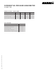
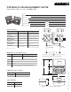

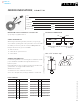
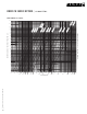
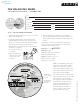
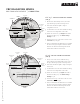
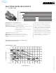
Table Of Contents
- commercial & residential pumps
- Design Envelope Compass Circulators
- Astro 2 Circulators
- Astro 2 Hot Water Recirculation Systems
- Astro 2 24-hour timer
- Aquastat controls
- Astro Express 2 Hot Water Recirculation
- S&H 3-Piece Circulators
- 1050 & 1060 3-Piece Circulators
- E.2 Circulators
- E.2 Circulator Spool Pieces
- 4270 & 4270 Stock Motor Mounted Pumps
- 4360 Pump-in-a-Box
- 4380 Pump-in-a-Box
- Design Envelope 4300/4380 Pump-in-a-Box
- hydronic specialties
- circuit balancing valves (cbv)
- replacement parts
- parts look up
- competition circulator cross reference
- technical data
- Pump Formulas
- Pressures & Altitudes
- Freezing & Boiling Points
- Ethylene Glycol Properties
- Propylene Glycol Properties
- Water Properties
- Useful System Curve Formulas
- Pipe Maximum Pressures
- Hydraulic Resistance
- Pipe Information
- Pipe Fittings & Valves Friction Loss
- Water Flow Calculator
- Unit Conversions
- Typical Symbols
- Product Solution Outlines/Brochures

88
|
HYDRONIC SOLUTIONS CATALOG
CBV BALANCING WHEEL
CBV FLOW MEASUREMENT
|
SUBMITTAL
2½" & 3" circuit balancing valves
(fig. 3)
1 Measure the dierential pressure (
P) in the
pipe with an appropriate measuring device.
2 Determine whether straight or angled
configuration is used.
3 Set the hairline over the valve handwheel setting
of the size and configuration of the valve.
4 In this case we have a 3" straight valve with a
handwheel setting of “3”. The Meter Gauge
Reading is 10 ft.
5 Read across from 10 on the lower scale to reveal
a Flow rate of 6 USgpm.
6 In the event that the calculated flow is not within
the desired range, turning the handle clockwise
will decrease the flow and turning the handle
anticlockwise will increase the flow.
4"-12" circuit balancing valves
(fig. 4)
1 The process is the same as with the 2½ & 3"
valves. Measure the dierential pressure (
P) in
the pipe with an appropriate measuring device.
2 Determine whether straight or angled configura-
tion is used.
3 Set the hairline over the valve handwheel setting
of the size and configuration of the valve.
4 In this case we have a 8" angled valve with a
handwheel setting of “7”. The Meter Gauge
Reading is 15 ft.
5 Read across from 15 on the lower scale to reveal
a Flow rate of 1550 USgpm.
6 In the event that the calculated flow is not within
the desired range, turning the handle clockwise
will decrease the flow and turning the handle
anticlockwise will increase the flow.
60
CBV size (inches)
CBV size (inches)
3
valve size
CBV Rule
Armstrong Circuit Balancing Valves include an integral fixed orifice
venturi for dierential pressure to flowrate correlation.
Compared to traditional variable orifice valves, the handle
turns position is not required for flow rate calculation.
This design enables faster and more accurate flow
measurement, cbv adjustment, system balancing and
troubleshooting.
Accurate balancing contributes to greater
occupant comfort, system eciency and
life expectancy.
Flow Rate = 0.66C
V
∆P/(d/62.4)
instructions (For balancing purposes only)
Use Armstrong performance curves for valve pressure drop determination
and size selection.
1. Measure the dierential pressure across ports a & b of the cbv.
2.
Slide the wheel to the nearest corresponding value in the
∆
p(ft) window.
3. Read the flow rate conversions (feet to USgpm) in the red USgpm
window for the cbv model measured.
Alternatively, or if a more precise flow rate calculation is
required, use the flow rate formula and corresponding
Cv value for the cbv model measured.
flow rate: USgpm
∆P: dierential pressure (ft)
d: density of liquid (lb/ft
3
)
d/62.4: 1 for water at 60˚f (16˚c)
0.66: conversion constant
Cv: cbv flow co-ecient
©
2
0
1
3
a
r
m
s
t
r
o
n
g
fl
u
i
d
t
e
c
h
n
o
l
o
g
y
|
p
n
:
5
7
0
1
0
9
-
2
0
3
(
f
e
e
t
o
f
w
a
t
e
r
)
m
e
t
e
r
g
a
u
g
e
r
e
a
d
i
n
g
fl
o
w
r
a
t
e
(
g
p
m
)
Valve handwheel setting
instructions
1. Place hairline over valve setting opposite cbv size.
2. Read flow rate (gpm) opposite meter gauge reading.
USgpm
size
Cv
USgpm
size
Cv
meter gauge
scale
valve handle
position
straight
valves
angl
ed
valves
hairlin
e
flow rate
scale
valve handle
position
straight
valves
hairlin
e
meter gauge
scale
angl
ed
valves
1 500
dp (psi)
d
gpm = c
v
c
v
valve coecient
(gpm at 1 psi pressure drop)
c
v
=1.16 k
v
d=Density of the
liquid with d=1 for
water at 60˚f
(
f
e
e
t
o
f
w
a
t
e
r
)
m
e
t
e
r
g
a
u
g
e
r
e
a
d
i
n
g
fl
o
w
r
a
t
e
(
g
p
m
)
CBV size (inches)
CBV size (inches)
instructions
1. Place hairline over valve setting opposite cbv size.
2. Read flow rate (gpm) opposite meter gauge reading.
°F
°C
C%
0
10
20
30
40
50
40
4.5
Cg
1.0
.99
.99
.98
.97
.96
70
21
Cg
1.0
.99
.99
.98
.97
.96
70
21
Cg
1.0
.99
.99
.99
.98
.98
180
82
Cg
1.01
1.01
1.0
1.0
.99
.98
40
4.5
Cg
1.0
.99
.99
.99
.98
.97
180
82
Cg
1.01
1.01
1.01
1.01
1.0
1.0
propylene
ethelene
Glycol corrections
gpm (actual) = gpm (tested) × Cg
model
2½" – 12"
pipe size
inches
c
v
fully
open
minimum flow
1ft pressure drop
50% open
gpm
100% open
gpmgpm
pressure
drop (ft)
velocity
(ft/s)
7.0
7.0
7.0
7.8
8.8
7.05
7.32
7.45
2½
3
4
5
6
8
10
12
cbv 2½ g/a
cbv 3 g/a
cbv 4 g/a
cbv 5 g/a
cbv 6 g/a
cbv 8 g/a
cbv 10 g/a
cbv 12 g/a
69.0
97.0
255.0
324.0
449.0
1127.0
2050.0
3125.0
18.0
19.0
46.0
60.0
100.0
307.0
559.0
1532.0
46.0
64.0
180.0
220.0
300.0
751.0
1347.0
2059.0
100.0
160.0
275.0
500.0
800.0
1100.0
1800.0
2600.0
4.5
11.0
2.8
5.5
7.0
2.1
1.8
1.5
maximum
recommended flow
valv e sizing chart
armstrongfluidtechnology.com
valve size
flow rate
scale
8
fig. 3
fig. 4