
Replacement Parts

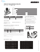

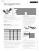
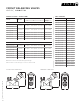
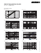

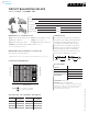
Table Of Contents
- commercial & residential pumps
- Design Envelope Compass Circulators
- Astro 2 Circulators
- Astro 2 Hot Water Recirculation Systems
- Astro 2 24-hour timer
- Aquastat controls
- Astro Express 2 Hot Water Recirculation
- S&H 3-Piece Circulators
- 1050 & 1060 3-Piece Circulators
- E.2 Circulators
- E.2 Circulator Spool Pieces
- 4270 & 4270 Stock Motor Mounted Pumps
- 4360 Pump-in-a-Box
- 4380 Pump-in-a-Box
- Design Envelope 4300/4380 Pump-in-a-Box
- hydronic specialties
- circuit balancing valves (cbv)
- replacement parts
- parts look up
- competition circulator cross reference
- technical data
- Pump Formulas
- Pressures & Altitudes
- Freezing & Boiling Points
- Ethylene Glycol Properties
- Propylene Glycol Properties
- Water Properties
- Useful System Curve Formulas
- Pipe Maximum Pressures
- Hydraulic Resistance
- Pipe Information
- Pipe Fittings & Valves Friction Loss
- Water Flow Calculator
- Unit Conversions
- Typical Symbols
- Product Solution Outlines/Brochures

CIRCUIT BALANCING VALVES
MINI SWEAT
|
SUBMITTAL
63
|
HYDRONIC SOLUTIONS CATALOG
Job:
Representative:
Engineer:
Contractor:
Order no: Date:
Submitted by: Date:
Approved by: Date:
cbvs must be installed for flow in the
direction of the arrow on the valve body
and to allow easy access to the metering
ports and handwheel.
note: We recommend that the valve be
installed in such a way that the meter
connections be above or on the side of the
valve body. (Not below or at 6 o’clock).
mounting orientation
specification
Connection: Solder joint Material of construction : Brass
Handwheel: 1 turn 360°
ma ximum pump oper ating cond itions
300 psig at 250°f (2068 kPa at 121°c)
0.0 0.5 1.0 1.5 2.0 2.5 3.0 3.5 4.0 4.5 5.0 5.5 6.0
0.2 0.3 0.4 0.5 0.6 0.7 0.8 0.9
100
90
80
70
60
50
40
30
20
10
0
cbv - ½"ms
flow rate - USgpm
pressure drop - in. wg
handwheel position
0.0 0.5 1.0 1.5 2.0 2.5 3.0 3.5 4.0 4.5 5.0 5.5 6.0 6.5 7.0
flow rate - USgpm
pressure drop - in. wg
handwheel position
0.2 0.3 0.4 0.5 0.6 0.7 0.8 0.9
100
90
80
70
60
50
40
30
20
10
0
7.5 8.0 8.5 9.0
cbv - ¾"ms
performance curve
model no. quantity identification
c
a
b
model part number
CBV-K"MS 570109-332
CBV-O"MS 570109-333
part numbers
dimension data - inches (mm)
model pipe size a b c weight
CBV-K"MS K" 3.12 (79) 3.53 (90) 1.34 (34) 1.10 (0.50)
CBV-O"MS O" 3.78 (96) 3.62 (92) 1.34 (34) 1.19 (0.54)
All dimensions are in inches (mm) and weights are in lbs (kg)
Solder style models are supplied unassembled. Valve body must be soldered in the line before assembly.
Refer to Cv curves for sizing and balancing, giving pressure drop at dierent settings and flow rates.
Suggested meters for use in conjunction with Armstrong cbvs are the cbdm-200, cbdm-135/60, dpm-15
and dpm-100.
All valves furnished with probe metering ports.
back to
contents
<