
Replacement Parts

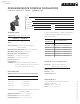
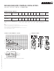
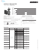
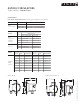
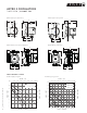


Table Of Contents
- commercial & residential pumps
- Design Envelope Compass Circulators
- Astro 2 Circulators
- Astro 2 Hot Water Recirculation Systems
- Astro 2 24-hour timer
- Aquastat controls
- Astro Express 2 Hot Water Recirculation
- S&H 3-Piece Circulators
- 1050 & 1060 3-Piece Circulators
- E.2 Circulators
- E.2 Circulator Spool Pieces
- 4270 & 4270 Stock Motor Mounted Pumps
- 4360 Pump-in-a-Box
- 4380 Pump-in-a-Box
- Design Envelope 4300/4380 Pump-in-a-Box
- hydronic specialties
- circuit balancing valves (cbv)
- replacement parts
- parts look up
- competition circulator cross reference
- technical data
- Pump Formulas
- Pressures & Altitudes
- Freezing & Boiling Points
- Ethylene Glycol Properties
- Propylene Glycol Properties
- Water Properties
- Useful System Curve Formulas
- Pipe Maximum Pressures
- Hydraulic Resistance
- Pipe Information
- Pipe Fittings & Valves Friction Loss
- Water Flow Calculator
- Unit Conversions
- Typical Symbols
- Product Solution Outlines/Brochures

4
|
HYDRONIC SOLUTIONS CATALOG
DESIGN ENVELOPE COMPASS CIRCULATORS
VARIABLE SPEED WET ROTOR
|
SUBMITTAL
compass performance curves
pc4
pc3
pc2
pc1
i
ii
iii
speed pressure curve
auto
compass performance curves
pc1
pc2
pc3
pc4
iii
ii
head - ft.wg.
flow - usgpm
i
20
22
24
20 22
18
18
16
16
14
14
12
12
10
10
8
8
4
4
6
6
2
2
0
0
auto
Lights on the display indicate the Control mode selected.
dimensions and weights
stainless steel* part number a b c d e f g
connection
type& size
weight
Compass 20-20 ss
flange
180203-607
6.50
(165)
7.08
(180)
5.75
(146)
4.00
(102)
2.00
(50)
3.25
(80)
5.31
(135)
Flange – (2) ½"
dia. bolt holes
8.0 (3.6)
cast iron part number a b c d e f g
connection
type & size
weight
Compass 20-20 ci
flange
180203-606
6.50
(165)
7.08
(180)
5.75
(146)
4.00
(102)
2.00
(50)
3.25
(80)
5.31
(135)
Flange – (2) ½"
dia. bolt holes
8.0 (3.6)
note:
All dimensions are in inches (mm) and weights in lbs (kg).
*Certified <0.25 weighted average percent lead and complies with California Health and
Safety Code Section 116875 (commonly known as ab 1953).
** For open systems, it is recommended that the liquid temperature be less than 150°f
(65°c) to avoid precipitation of calcium.
e
f
d
b
c
a
g
(on center)
compass flange