
Replacement Parts
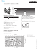
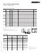

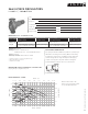
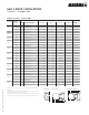
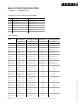

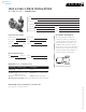
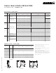
Table Of Contents
- commercial & residential pumps
- Design Envelope Compass Circulators
- Astro 2 Circulators
- Astro 2 Hot Water Recirculation Systems
- Astro 2 24-hour timer
- Aquastat controls
- Astro Express 2 Hot Water Recirculation
- S&H 3-Piece Circulators
- 1050 & 1060 3-Piece Circulators
- E.2 Circulators
- E.2 Circulator Spool Pieces
- 4270 & 4270 Stock Motor Mounted Pumps
- 4360 Pump-in-a-Box
- 4380 Pump-in-a-Box
- Design Envelope 4300/4380 Pump-in-a-Box
- hydronic specialties
- circuit balancing valves (cbv)
- replacement parts
- parts look up
- competition circulator cross reference
- technical data
- Pump Formulas
- Pressures & Altitudes
- Freezing & Boiling Points
- Ethylene Glycol Properties
- Propylene Glycol Properties
- Water Properties
- Useful System Curve Formulas
- Pipe Maximum Pressures
- Hydraulic Resistance
- Pipe Information
- Pipe Fittings & Valves Friction Loss
- Water Flow Calculator
- Unit Conversions
- Typical Symbols
- Product Solution Outlines/Brochures

S&H 3-PIECE CIRCULATORS
H MODELS
|
SUBMITTAL
25
|
HYDRONIC SOLUTIONS CATALOG
Job:
Representative:
Engineer:
Contractor:
Order no: Date:
Submitted by: Date:
Approved by: Date:
The pump should be installed in a position to permit proper
lubrication of bearings and servicing. Motor and bearing
bracket are to be kept free of insulation. Pump and motor
unit are designed to be supported by the in line piping
only. Do not support in any other manner. A height of
approximately 4 feet above floor is recommended.
materials of construction
ma ximum pump oper ating conditio ns
mounting orientation
125 psig at 225°f (863 kPa at 107°c)
Based on 1800 rpm, 60 Hz motors. For 50 Hz motors write for special capacity charts.
flow - usgpm
flow - l/s
head - feet
head - metres
0 0.63 1.89 3.15 4.41 5.68 6.94 8.209.4610.73
01030507090 110 130 150 170
0
10
20
30
50
40
0
3.0
6.1
9.1
15.2
12.1
H5
H4
H6
H6
H6
H6
H6
H6
H5
H5
H5
H3
Based on 1800 rpm, 60 Hz
motors. For 50 Hz motors write
for special capacity charts.
performance curve
horizontal mounting
part name
h-32 to h-54
bronze fitted
h-63 to h-68
bronze fitted
h-32 to h-54
lead free bronze*
h-63 to h-68
lead free bronze*
Pump body Cast iron Cast iron Lead free bronze Lead free bronze
Coupler
h-32 & h-41 flexible, 4-spring
h-51 to h-54 flexible, spacer type
Flexible, spacer type
h-32 & h-41 flexible, 4-spring
h-51 to h-54 flexible, spacer type
Flexible, spacer type
Impeller: Non-ferrous
Bearings: Sleeve - Oil lubricated**
Maintenance free - Permanently lubricated***
Seal: Mechanical
Stationary seal face: Sintered silicon carbide
* Contains less than 0.25% lead, weighted average.
** Alloy shaft with copper sleeve.
*** Stainless steel shaft.