Hydronic solutions c a ta lo g e. 2 circulators file no: 10.01 date: november 2014 supersedes: 10.
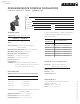
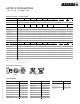
to < back contents DESIGN ENVELOPE COMPASS CIRCULATORS VARIABLE SPEED WET ROTOR | S U B M I T T A L Job: Representative: Engineer: Contractor: Order no: Date: Submitted by: Date: Approved by: Date: technical data Supply voltage: 1 × 115 v – 10%/+ 6%, 60 Hz minimum ma ximum Amp 0.05 0.65 Watt 5 45 Motor protection: The pump requires no external motor protection. Maximum working temperature: 230°f (110°c) maximum Maximum working pressure: 150 psi (10 bar).
DESIGN ENVELOPE COMPASS CIRCULATORS VARIABLE SPEED WET ROTOR | S U B M I T T A L dimensions and weights a b c d e f g connection t ype& size weight 6.50 (165) 7.08 (180) 5.75 (146) 4.00 (102) 2.00 (50) 3.25 (80) 5.31 (135) Flange – (2) ½" dia. bolt holes 8.0 (3.6) a b c d e f g connection t ype & size weight 6.50 (165) 7.08 (180) 5.75 (146) 4.00 (102) 2.00 (50) 3.25 (80) 5.31 (135) Flange – (2) ½" dia. bolt holes 8.0 (3.
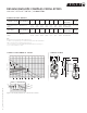
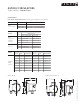
to < back contents ASTRO 2 CIRCULATORS THREE SPEED | S U B M I T T A L Job: Representative: Engineer: Contractor: Order no: Date: Submitted by: Date: Approved by: Date: tech nic al data materials of construction Flow range: 0 to 64 USgpm (0 to 4.04 L/s) Pump body: Cast iron (closed systems) Head range: 0 to 42.0 feet (0 to 12.8 m) Lead free bronze* (open systems) Maximum fluid temperature: 185°f / 85°c (astro 286 up to 1.35a) 150°f / 65°c (astro 286 over 1.
ASTRO 2 CIRCULATORS THREE SPEED | S U B M I T T A L dimension data - inches (mm) lead free bronze* a b c d e f Astro 225bs ½" swt 5.00 (127) 5.00 (127) 4.13 (105) — 3.00 (76) — Sweat – ½" 6.0 (2.7) Astro 225bs ¾" swt 5.00 (127) 5.00 (127) 4.13 (105) — 3.00 (76) — Sweat – ¾" 6.0 (2.7) stainless steel* a b c d e f Astro 220ssu** 6.00 (152) 5.00 (127) 4.00 (102) — 3.00 (76) — Union – 1¼" npsm 6.5 (2.9) Astro 225ssu** 6.00 (152) 5.00 (127) 4.00 (102) — 3.
ASTRO 2 CIRCULATORS THREE SPEED | S U B M I T T A L accessories lead free* union fitting sets (contains two (2) half unions and gaskets) connection 810120-320 1.25" npsm × 0.5" sweat lead free 810120-322 1.25" npsm × 0.75" sweat lead free 810120-324 1.25" npsm × 0.75" fnpt lead free model size Astro 210/230/250 /280/286 Compass Astro 290 model 0.75" 816013-841 816013-111 1" 816012-841 816012-111 1.25" 816011-841 816011-111 1.5" 816009-841 816009-111 1" 806073-841 806073-111 1.
ASTRO 2 CIRCULATORS THREE SPEED | S U B M I T T A L astro 230ss/ci, 250ss/ci astro 230ci-r, 250ci-r b e c b e a c a f f (on center) d (on center) d astro 280ss, 210ci/ss astro 280ci, 29 0ci/ss, 286ci/ss b e c b e a c a f f (on center) (on center) d d per fo r m an ce cu rve 0 0.13 0.38 0.25 0.50 0.88 4.3 28 3.7 24 3.0 2.4 2 6 1.8 1 20 head - feet 3 8 astro 250 astro 230 astro 220 7.3 6.1 2 4.9 12 8 2 0.6 4 0 0 0 2 0.13 0.25 0.38 0.50 0.
ASTRO 2 CIRCULATORS THREE SPEED | S U B M I T T A L astro 210, 29 0 head - feet 20 0 0.25 0.50 0.76 1.01 1.26 1.51 1.77 2.02 2.27 2.52 2.78 3.03 3.28 3.53 3.79 4.04 16 without check valve 3 with check valve 12 1 8 4 0 astro 210 astro 290 2 2 3 4.9 3.7 2.4 1.2 1 0 6.1 head - metres flow - l/s 4 8 12 16 20 24 28 32 36 40 44 48 52 56 60 64 0 flow - usgpm astro 280, 286 flow - l/s 2.02 2.52 13.
| HYDRONIC SOLUTIONS CATALOG
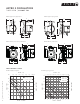
to < back contents ASTRO 2 | HOT WATER RE-CIRCULATION SYSTEMS S U B M I T TA L Job: Representative: Engineer: Contractor: Date: Submitted by: Date: Approved by: Date: application Flange size: Note: USgpm (L/s) Temperature: Capacity: Head: ft (m) Liquid: Companion flanges: Included: °f (°c) tech nic al data Power connection: 6.0 ft. (1.8 m) power cord, molded duplex plug with ground Environment: Indoor use only Flow range: 0 to 64 USgpm (0 to 4.
ASTRO 2 | HOT WATER RE-CIRCULATION SYSTEMS S U B M I T TA L dimension data - inches (mm) model a b c d e f astro 225bs 5.0 (127) 6. 5 (165) 5.6 (142) 7.1 (18 0) 4. 3 (110) 1.8 (46) astro 220/225ssu 5.0 (127) 5. 3 (134) 4.4 (112) 6. 3 (160) 3.4 (86) 1.8 (46) astro 230/250ss 6.4 (162) 8.7 (221) 6.8 (173) 7.0 (178) 3.7 (93) 1.
ASTRO 2 | HOT WATER RE-CIRCULATION SYSTEMS S U B M I T TA L lead free* union fitting sets (contains two (2) half unions and gaskets) model connection 810120-320 1.25" npsm × 0.5" sweat lead free 810120-322 1.25" npsm × 0.75" sweat lead free 810120-324 1.25" npsm × 0.75" fnpt lead free size Astro 210/230/250 /280/286 Compass Astro 290 flange kits item number lead free bronze* cast iron 0.75" 816013-841 816013-111 1" 816012-841 816012-111 1.25" 816011-841 816011-111 1.
ASTRO 2 | HOT WATER RE-CIRCULATION SYSTEMS S U B M I T TA L astro 225bs e astro 220/225ssu b f b d d a f e b f e d astro 230/250ss a a c c c per fo r m an ce cu rve 0 0.13 0.38 0.25 0.50 0.63 0.76 0.88 astro 225bs astro 225ssu 12 28 3.7 24 3.0 2.4 2 6 1.8 1 20 head - feet 3 8 astro 250 astro 230 astro 220 7.3 6.1 2 4.9 12 8 2 0.6 4 0 0 0 2 0.13 0.25 0.38 0.50 0.63 0.76 0.88 1.01 1.14 8.5 16 1.2 4 1 0 3 10 head - feet 4.
to < back contents ASTRO 2 | 24 HOUR TIMER | S U B M I T TA L Job: Representative: Engineer: Contractor: Order no: Date: Submitted by: Date: Approved by: Date: tag no. model no.
| HYDRONIC SOLUTIONS CATALOG
to < back contents AQUASTAT CONTROLS ½” & ¾” | S U B M I T T A L Job: Representative: Engineer: Contractor: Order no: Date: Submitted by: Date: Approved by: Date: technical data j Description: Aquastat (thermostatic) switch a Application: Clip-on thermostatic control for Astro circulators h Type: Bi-metallic disc, snap-acting Enclosure: Environmentally sealed b g Mounting: Clip-on mount for ½" (12.7 mm) i.d. copper tube [X" (15.8 mm) o.d.
AQUASTAT CONTROLS ½” & ¾” | S U B M I T T A L wiring diagram black white green white black black white astro series circulator with aquastat control wiring diagram astro series circulator with 24 hour timer and aquastat control wiring diagram LNG black pump L black white black aquastat HYDRONIC SOLUTIONS CATALOG astro 2 series circulator with aquastat control wiring diagram | N white G green black black white timer green 18 pump ground screw aquastat pump black timer green white bl
to < back contents ASTRO EXPRESS 2 HOT WATER RECIRCULATION | S U B M I T TA L Job: Representative: Engineer: Contractor: Order no: Date: Submitted by: Date: Approved by: Date: technical data quantity description *Astro Express 2 system (Wet rotor circulator with timer, line cord, union hardware, and one Astro Express lf valve) *Astro Express lf valve (only) for lengthy branches to additional faucets off main distribution pipe materials of construction astro expre
ASTRO EXPRESS 2 | HOT WATER RECIRCULATION S U B M I T TA L dimension data - inches (mm) dimensions inches (mm) product a Astro Express 2 circulator Astro Express lf valve weight b c d 6.0 0(152) 5.0 0 (127) 4.0 0 (102) 2.50 (63) 1.50 (38) 2.10 (53) astro express lf valve hot cold 5.0 0 (127) 1.8 0 (46) 2.60 (66) 0.
to < back contents S&H 3-PIECE CIRCULATORS S MODELS | S U B M I T T A L Job: Representative: Engineer: Contractor: Order no: Date: Submitted by: Date: Approved by: Date: mounting orientation m aterial s o f co n struc tio n part name bronze fitted lead free bronze* Pump Body Cast iron Lead free Bronze The pump should be installed in a position to permit proper lubrication of bearings and servicing. Motor and bearing bracket are to be kept free of insulation.
S&H 3-PIECE CIRCULATORS S MODELS | S U B M I T T A L dimension data - inches (mm) model flange size (n.p.
S&H 3-PIECE CIRCULATORS S MODELS | S U B M I T T A L cast iron lf bronze O 116013- 011 116013- 841 1 116012- 011 116012- 841 1N 116011- 011 116011- 841 1K 1160 09 - 011 1160 09 - 841 2 105210 - 011 /10 6074- 011 105210 - 841 /10 6074- 841 2K 105189 - 011 105189 - 841 3 10518 8- 011 /133615 - 010 10518 8- 841 /10 6466 - 841 | size HYDRONIC SOLUTIONS CATALOG companion single flange part numbers 23
| HYDRONIC SOLUTIONS CATALOG
S&H 3-PIECE CIRCULATORS H MODELS | S U B M I T T A L Job: Representative: Engineer: Contractor: Order no: Date: Submitted by: Date: Approved by: Date: m aterial s o f co n struc tio n part name h-32 to h-54 bronze fitted h-63 to h-68 bronze fitted h-32 to h-54 lead free bronze* h-63 to h-68 lead free bronze* Pump body Cast iron Cast iron Lead free bronze Lead free bronze Coupler h-32 & h-41 flexible, 4-spring Flexible, spacer type h-51 to h-54 flexible, spac
S&H 3-PIECE CIRCULATORS H MODELS | S U B M I T T A L dimension data - inches (mm) model H32 H41 H51 H52 H53 H54 H63 H64 H65 H66 H67 | HYDRONIC SOLUTIONS CATALOG H68 26 motor** flange size (n.p.
S&H 3-PIECE CIRCULATORS H MODELS | S U B M I T T A L companion single flange part numbers size cast iron lf bronze O 116013- 011 116013- 841 1 116012- 011 116012- 841 1N 116011- 011 116011- 841 1K 1160 09 - 011 1160 09 - 841 2 105210 - 011 /10 6074- 011 105210 - 841 /10 6074- 841 2K 105189 - 011 105189 - 841 3 10518 8- 011 /133615 - 010 10518 8- 841 /10 6466 - 841 part numbers bronze fitted item no. lead free* bronze bronze fitted item no. item no. lead free* bronze item no.
| HYDRONIC SOLUTIONS CATALOG
to < back contents 1050 & 1060 3-PIECE CIRCULATORS CUSTOM IN-LINE | S U B M I T T A L Job: Representative: Engineer: Contractor: Order no: Date: Submitted by: Date: Approved by: Date: pump de sig n data mounting orientation Pump model: Flange size: No.
1050 & 1060 3-PIECE CIRCULATORS CUSTOM IN-LINE | S U B M I T T A L motor data - inches (mm) motor pump size hp N L 1050 K O 1060 1.5D resilient mount inches (mm) phase and volt a c k 1 phase 115 v 17.25 (438) 13.50 (343) 7.38 (187) 1 phase 115/230 v or 3 phase 208230/460 v or 575 v 19.75 (502) 16.00 (406) 20.00 (508) l m n lbs (kg) — — — — — — 9.88 (251) — — — 58 (26) 16.50 (419) 10.38 (264) — — — 75 (34) 48 (22) 1 20.75 (527) 17.00 (431) 10.
1050 & 1060 3-PIECE CIRCULATORS CUSTOM IN-LINE | S U B M I T T A L per fo r m an ce cu rve rpm: 1800 Availability: 1050 all ratings • bhp based on shown Fluid’s sp. gr. • Performance guaranteed only at operating point indicated. • Curve shown for clear, cold water – sp. gr. 1.0000 Curve number: pt25-0-0-1800 Size: 1b Curve number: pt1-1-0-1800 5.25 in 5.25 in 29 29 36 (7.6) 25 41 45 (6.1) 20 (6.1) 20 4.50 in 49 4.25 in (4.6) 15 50 48 51 4.00 in 52 45 0.5 hp 41 (3.0) 10 0.333 hp 0.
1050 & 1060 3-PIECE CIRCULATORS CUSTOM IN-LINE | S U B M I T T A L per fo r m an ce cu rve rpm: 1800 Availability: 1060 all ratings • bhp based on shown Fluid’s sp. gr. • Performance guaranteed only at operating point indicated. • Curve shown for clear, cold water – sp. gr. 1.0000 Curve number: pt8-0-0-1800 7.00 in 23 33 40 (15.2) 50 Size: 1.5d 45 48 51 48 6.00 in 45 5.50 in 40 5.00 in 33 (6.1) 20 1.5 hp 1 hp 0.75 hp (3.0) 10 0 (0.00) 40 (2.
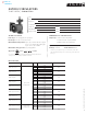
to < back contents E.2 CIRCULATORS | S U B M I T TA L Job: Representative: Engineer: Contractor: Order no: Date: Submitted by: Date: Approved by: Date: m aterial s o f co n struc tio n technical data Pump body: Cast iron (closed sytems) Bronze (lead free for open systems) Flow range: 0 to 128.0 USgpm (0 to 8.1 L/s) Head range: 0 to 61.0 feet (0 to 18.6 m) Max/Min fluid temp: 230°f/40°f (110°c/4°c) Max.
E.2 CIRCULATORS | S U B M I T TA L | HYDRONIC SOLUTIONS CATALOG dimension data - inches (mm) 34 model body e7.2 e7.2b e8.2 e8.2b e9.2 e9.2b e10.2 e10.2b e11.2 e11.2b e13.2 e13.2b e16.2 e16.2b e30.2–2” e30.2b–2” e30.2–3” e30.2b–3” e33.2–2” e33.2b–2” e33.2–3” e33.2b–3” e12.2 e12.2b e14.2 e14.2b e15.2 e15.2b e17.2 e17.2b e19.2 e19.2b e21.2 e21.2b e22.2 e22.2b e23.2 e23.2b e24.2 e24.2b e28.2 e28.2b e29.2 e29.
E.2 CIRCULATORS | S U B M I T TA L moto r data e8.2/ e8.2b e9.2/ e9.2b e10.2/ e10.2b e11.2/ e11.2b e13.2/ e13.2b e16.2/ e16.2b 120v 208v 240v full load amp nominal draw (a) power (w) 2.0 1.0 1.0 2.0 1.0 e30.2/ e30.2b 120v 208v 240v 277v 4.1 2.4 2.4 2.4 e33.2/ e33.2b 120v 208v 240v 277v 5.7 3.1 3.1 3.1 120v 4.8 120v 208v 240v 277v 120v 208v 240v 277v 120v 208v 240v 277v 120v 208v 240v 277v 120v 208v 240v 277v 120v 208v 240v 277v 120v 208v 240v 277v 120v 208v 240v 277v 2.5 1.8 1.8 1.8 3.0 1.
E.2 CIRCULATORS | S U B M I T TA L part numbers | HYDRONIC SOLUTIONS CATALOG model 36 e7.2 e7.2b e8.2 e8.2b e9.2 e9.2b e10.2 e10.2b e11.2 e11.2b e13.2 e13.2b e16.2 e16.2b e30.2–2" e30.2b–2" e30.2–3" e30.2b–3" e33.2–2" e33.2b–2" e33.2–3" e33.2b–3" e12.2 e12.2b e14.2 e14.2b e15.2 e15.2b e17.2 e17.2b e19.2 e19.2b e21.2 e21.2b e22.2 e22.2b e23.2 e23.2b e24.2 e24.2b e28.2 e28.2b e29.2 e29.
to < back contents E.2 CIRCULATOR SPOOL PIECES | S U B M I T TA L Job: Representative: Engineer: Contractor: Order no: Date: Submitted by: Date: Approved by: Date: model pipe size a inches (mm) spool length b inches (mm) bolt holes c inches (mm) part no. esp-1 1. 25 (32) 3.0 0 (75) 3.16 (8 0) 18 0221- 011 esp-2 1. 25 (32) 2. 50 (64) 3.16 (8 0) 18 0222- 011 esp-4 1. 50 (38) 3.0 0 (75) 3.44 (87) 18 0224- 011 esp-5 1. 50 (38) 5.0 0 (125) 3.
E.2 CIRCULATOR SPOOL PIECES | pump model to be replaced and upgraded upgrade with esp model to use e model + with e series bell & gossett 2.
to < back contents 4270 PUMPS | MOTOR MOUNTED S U B M I T TA L Job: Representative: Engineer: Contractor: Order no: Date: Submitted by: Date: Approved by: Date: m aterial s o f co n struc tio n mounting orientation Construction: Bronze Fitted O-ring: Viton Impeller: Ultem Adapter: Aluminum Casing/Volute: Cast iron Shaft: 416 Stainless steel Mount the pump on a foundation sufficiently substantial to absorb any vibration.
4270 PUMPS MOTOR MOUNTED | S U B M I T TA L dimension data - inches (mm) model suction discharge impeller size motor dimensions inches (mm) hp a b c l* weight t w x y 702** 1.25 (31) 1.00 (25) 3.50 (88) ¾ 704** 1.25 (31) 1.00 (25) 4.00 (100) 1 705** 1.25 (31) 1.00 (25) 4.50 (114) 1½ 706** 1.50 (38) 1.25 (31) 4.50 (114) 2 51 (113) 707** 2.00 (50) 1.50 (38) 4.00 (100) 1½ 53 (117) 709T 2.00 (50) 1.50 (38) 4.38 (111) 2 2.90 4.80 3.80 8.80 3.10 8.50 4.20 4.
to < back contents 4360 PUMP-IN-A-BOX CLOSE-COUPLED VIL PUMPS | S U B M I T T A L Job: Representative: Engineer: Contractor: Order no: Date: Submitted by: Date: Approved by: Date: m aterial s o f co n struc tio n mechanical seal design data Casing: Cast iron Motor shaft: Carbon steel s t y le Companion flanges: Cast iron Stub shaft (4360 b): Stainless steel Motor/pump bracket: Cast iron Shaft sleeve (4360 d): Bronze Type Impeller: Bronze Rotating face Statio
4360 PUMP-IN-A-BOX CLOSE-COUPLED VIL PUMPS | S U B M I T T A L motor data - inches (mm) performance c urve model 02b part number 208 -230/460 volts 575 volts inlet & outlet hp (npt ) 4360b-1205t-1.5/2 4360b00ah-083 4360b00ah-068 1.25"µ1.25" 1 1.5 02d 4360b-1205t-2.0/2 4360b00aj-083 4360b00aj-068 1.25"µ1.25" 1 2 04b 4360b-1505t-0.5/4 1.5"µ1.5" 2 0.5 04f 4360b-1505t-3.0/2 1.5"µ1.5" 1 3 06b 4360b-2205t-0.5/4 2"µ2" 2 0.5 06d 4360b-2205t-0.
60 PUMP-IN-A-BOX CLOSE-COUPLED VIL PUMPS | S U B M I T T A L installation mounted on rigid base without flexible connectors HYDRONIC SOLUTIONS CATALOG motor lifting hook supported | hanger supported pipe mounted 43
| HYDRONIC SOLUTIONS CATALOG
4380 PUMP-IN-A-BOX CLOSE-COUPLED VIL PUMPS | S U B M I T T A L Job: Representative: Engineer: Contractor: Order no: Date: Submitted by: Date: Approved by: Date: m aterial s o f co n struc tio n mechanical seal design data Casing: Cast iron Motor shaft: Carbon steel s t y le i n s i d e s i n g le s p r i n g Companion flanges: Cast iron Shaft sleeve: Bronze Type Armstrong 2a Impeller: Bronze Gasket: Non-asbestos fiber Rotating face Carbon Stationary face
4380 PUMP-IN-A-BOX CLOSE-COUPLED VIL PUMPS | S U B M I T T A L motor data - inches (mm) part number performance c urve model 14d 14f 16b 16d 18b 18d 18f 20d 22b 22d 22f 24b 24d 26b 26d 28f 4380-1508f-1.5/4 4380-1508f-2.0/4 4380-2206f-1.0/4 4380-2206f-1.5/4 4380-2208f-2.0/4 4380-2208f-3.0/4 4380-2208f-5.0/4 4380-2210f-5.0/4 4380-3306f-1.0/4 4380-3306f-1.5/4 4380-3306f-2.0/4 4380-3308f-3.0/4 4380-3308f-5.0/4 4380-3310f-5.0/4 4380-3310f-7.5/4 4380-4406f-3.
4380 PUMP-IN-A-BOX CLOSE-COUPLED VIL PUMPS | S U B M I T T A L installation mounted on rigid base without flexible connectors HYDRONIC SOLUTIONS CATALOG motor lifting hook supported | hanger supported pipe mounted 47
| HYDRONIC SOLUTIONS CATALOG
DESIGN ENVELOPE 4300/4380 PUMP-IN-A-BOX VERTICAL IN-LINE PUMPS | S U B M I T T A L Job: Representative: Engineer: Contractor: Order no: Date: Submitted by: Date: Approved by: Date: m aterial s o f co n struc tio n drive data Construction: bf with ansi 125 flanged connection Casing (volute): Cast iron (a48-30) Casing gasket: Confined Non-Asbestos Fiber Flush line: Braided Stainless Steel Impeller: Bronze Shaft sleeve (4380): Bronze Pump shaft (4300): ss astm a276 Type
DESIGN ENVELOPE 4300/4380 PUMP-IN-A-BOX VERTICAL IN-LINE PUMPS | S U B M I T T A L motor data - inches (mm) design envelope model part number inlet & outlet motor details ansi 125 hp* fr ame 208 -230 volts 460 volts 1 4380 1506-003.0 20212uegbnsxxxxx 20214uegbnsxxxxx 20215uegbnsxxxxx 2 4380 1508-001.5 3 4380 0206-001.5 4 575 volts 1.5"µ1.5" 1 3 182 22412uegbnsxxxxx 22414uegbnsxxxxx 22415uegbnsxxxxx 1.5"µ1.5" 1.5 145 21012uegbnsxxxxx 21014uegbnsxxxxx 21015uegbnsxxxxx 2 "µ2" 1.
DESIGN ENVELOPE 4300/4380 PUMP-IN-A-BOX VERTICAL IN-LINE PUMPS | S U B M I T T A L de 4380 de 4300 e f sd sd x t e f x t b b motor lifting hook supported mounted on rigid base without flexible connectors | hanger supported pipe mounted HYDRONIC SOLUTIONS CATALOG installation 51
| HYDRONIC SOLUTIONS CATALOG
to < back contents AUTOMATIC AIR VENTS HYDRONIC SPECIALTIES | S U B M I T T A L Job: Representative: Engineer: Contractor: quantity Order no: Date: Submitted by: Date: Approved by: Date: tag no. model no.
AUTOMATIC AIR VENTS HYDRONIC SPECIALTIES | S U B M I T T A L Models ava-013, -025 & -038 Models ava-050 with service check valve c c b Models ava-075 c b d d b a a a Models avv-050 with service check valve Models avv-038 c b Models avv-075 c d c b d b a a | HYDRONIC SOLUTIONS CATALOG part numbers 54 model part number ava- 013 272 0 0 5 -3 0 0 ava-025 272 0 0 5 -3 01 ava-038 272 0 0 5 -3 02 ava-050 272 0 0 5 -3 0 3 ava-075 272 0 0 5 -3 0 8 av v-038 272 0 0 5 -3 0 5 av
FLOAT TYPE AIR VENTS HYDRONIC SPECIALTIES | S U B M I T T A L Job: Representative: Engineer: Contractor: Order no: Date: Submitted by: Date: Approved by: Date: model number pipe size quantity required 67 V"(3.18)m 71 ¼"(6.35)m 72 V"(3.18)m 75 ½"(12.7)f & O"(19.05)m identification 7a overflow connector no. 67 auto-vent no. 71 auto-vent Vertical mounting V" i.p. Male connection. Up to 35 lbs. pressure 3¾ × 1I/af" Vertical mounting N" npt. Male connection.
| HYDRONIC SOLUTIONS CATALOG
to < back contents AIR REMOVAL TRAP HYDRONIC SPECIALTIES | S U B M I T T A L Job: Representative: Engineer: Contractor: Order no: Date: Submitted by: Date: Approved by: Date: de sig n fe atu r e s mounting orientation One piece heavy cast iron construction Suitable for pipe-line mounting Units painted gray enamel Arrow indicates direction of flow Use #67 auto air vent at top of 1"(25.4 mm) - 1.5" (38.1 mm) purgers Use #75 auto air vent at top on 2" (50.
| HYDRONIC SOLUTIONS CATALOG
to < back contents DIAPHRAGM EXPANSION TANK HYDRONIC SPECIALTIES | S U B M I T T A L Job: Representative: Engineer: Contractor: Order no: Date: Submitted by: Date: Approved by: Date: mounting orientation de sig n fe atu r e s Permanent air cushion Mild steel shell Enamel finish Eliminates water logging Diaphragm separates 12 psi air cushion from expanding system water Saves space and installation costs Multiple unit installation for larger volume capacity technical
DIAPHRAGM EXPANSION TANK HYDRONIC SPECIALTIES | S U B M I T T A L system connection charging valve system connection charging valve | HYDRONIC SOLUTIONS CATALOG part numbers 60 model part number 15 572 018 - 0 01 30 572 018 - 0 02 60 572 018 - 0 0 3 90 572 018 - 0 0 4 sx-30v 572 018 - 0 0 5 sx-40v 572 018 - 0 0 6 sx-60v 572 018 - 0 07 sx-90v 572 018 - 0 0 8 sx-110v 572018-009 sx-160v 572018-010
to < back contents RELIEF AND REDUCING VALVES HYDRONIC SPECIALTIES | S U B M I T T A L Job: Representative: Engineer: Contractor: Order no: Date: Submitted by: Date: Approved by: Date: mo u nt i n g o r i e ntati o n The pressure reducing valve should be installed with the flow arrow on the body pointing in the direction of the flow.
| HYDRONIC SOLUTIONS CATALOG
to < back contents CIRCUIT BALANCING VALVES MINI SWEAT | S U B M I T T A L Job: Representative: Engineer: Contractor: model no. Order no: Date: Submitted by: Date: Approved by: Date: quantity mounting orientation identification cbvs must be installed for flow in the direction of the arrow on the valve body and to allow easy access to the metering ports and handwheel.
| HYDRONIC SOLUTIONS CATALOG
to < back contents CIRCUIT BALANCING VALVES VENTURI | S U B M I T T A L Job: Representative: Engineer: Contractor: Order no: Date: Submitted by: Date: Approved by: Date: m aterial s o f co n struc tio n installation Body, bonnet: Brass alloy (forged) – cw602n Corrosion resistant to reference en12165 per iso-6509 ARMflo Circuit Balancing Valves are highly resistant to turbulence induced by nearby piping components and can often provide excellent results when mounted
CIRCUIT BALANCING VALVES VENTURI | S U B M I T T A L dimension data - inches (mm) model pipe size part numbers dimensions inches (mm) a b c weight model lbs (kg) cbv050v(s)cr-lf 57110 9 -370 solder joint connection cbv0 50vscr-lf cbv050v( t )cr-lf 57110 9 -3 6 0 3.19 (81) 4.56 (116) 2.76 (70) 1.05 (0.48) ¾" (dn20) 3.64 (93) 4.65 (118) 2.76 (70) 1.09 (0.49) 1" (dn25) 4.26 (108) 4.95 (126) 2.76 (70) 1.68 (0.76) cbv075v(s)cr-lf 57110 9 -371 cbv 125vscr 1¼" (dn32) 4.94 (125) 5.40 (137) 2.
CIRCUIT BALANCING VALVES VENTURI | S U B M I T T A L performance curves 3.0 10 cv 1 0.1 min. 10 cv 1 0.1 1 10 0.1 10 1 flow rate - gpm flow rate - gpm pressure drop ft. of h 2o min. 10 cv 1 max. 0.1 0 4. 0 5. 0 0 3. 0 2. 5 0. 100 1. 0 4. 5. 0 0 3. 2. 0 1. 0. 100 0 cbv075v(x )cr 5 cbv075v(x )cr-lf min. 10 cv 1 max. 0.1 0.1 10 1 flow rate - gpm 1 flow rate - gpm 10 100 pressure drop ft. of h 2o min. 10 cv 1 0 0 5. 4. 0 3. 0 0 2. 100 100 1.
| HYDRONIC SOLUTIONS CATALOG
to < back contents CIRCUIT BALANCING VALVES ANSI FLANGED | S U B M I T T A L Job: Representative: Engineer: Contractor: Order no: Date: Submitted by: Date: Approved by: Date: m aterial s o f co n struc tio n installation Body: Cast iron astm a48 class 30b Disk: Bronze astmb584 c-84400 Seat: epdm** elastomer Stem: Brass - astm b -16 Trim: Brass astm b283 c-37700 O-ring: Buna & epdm** elastomer Insulation: Optional fibre glass insulation with pvc cover ** epdm is not
CIRCUIT BALANCING VALVES ANSI FLANGED | S U B M I T T A L dimension data - inches (mm) model dimensions inches (mm) pipe size a b (full open) c weight d e f g s lbs (kg) 4.63 (118) 1.0 0 (25) 2. 56 (65) 7.0 0 (178) 12.0 0 33 (3 05) (15) 12.0 0 39 (3 05) (17.7) 125 # ansi fl ange cbv-2½fs cbv-2½fa cbv-3fs cbv-3fa cbv-4fs cbv-4fa cbv-5fs cbv-5fa cbv-6fs cbv-6fa cbv-8fs cbv-8fa cbv-10fs cbv-10fa cbv-12fs cbv-12fa 7. 38 (187) 2. 5 2.75 (70) 9.62 (244) 3 8.19 2.44 10.
CIRCUIT BALANCING VALVES ANSI FLANGED | S U B M I T T A L part numbers model part number model part number cbv-2½fs 570109 -376 cbv-10fs-125# 570109-382 cbv-2½fa 570109 -476 cbv-10fa-125# 570109-482 cbv-3fs 570109 -377 cbv-10fs-250# 570109-662 cbv-3fa 570109 -477 cbv-10fa-250# 570109-682 cbv-4fs 570109 -378 cbv-12fs-125# 570109-383 cbv-4fa 570109 -478 cbv-12fa-125# 570109-483 cbv-5fs 570109 -379 cbv-12fs-250# 570109-663 cbv-5fa 570109 -479 cbv-12fa-250# 570109-683 cbv-6fs
CIRCUIT BALANCING VALVES ANSI FLANGED | S U B M I T T A L performance curves 10 cv 1 100 1000 1 1000 HYDRONIC SOLUTIONS CATALOG | cv 1 1000 flow rate - gpm 10000 0 4. 0 10 2. 0 0 6. 0 5. 4. 0 3. 100 7.0 8.0 10.0 pressure drop ft. of h 2o pressure drop ft. of h 2o 100 0 c bv- 1 2 f s /c bv- 1 2 fa c bv- 1 0 f s /c bv- 1 0 fa 72 10000 flow rate - gpm flow rate - gpm 0.1 100 10 .0 12 .0 cv 0.1 100 10000 8. 0 10 3. 0.1 10 6. 0 4. 0 5. 0 6. 0 3. 0 4. 0 2. 0 1.
to < back contents CIRCUIT BALANCING VALVES ANSI GROOVED | S U B M I T T A L Job: Representative: Engineer: Contractor: Order no: Date: Submitted by: Date: Approved by: Date: m aterial s o f co n struc tio n installation Body: Ductile iron astm a536 gr65-45-12 Generally locate the valve five pipe diameters downstream from a fitting; with two diameters downstream from the balancing valve free from fittings.
CIRCUIT BALANCING VALVES ANSI GROOVED | S U B M I T T A L dimension data - inches (mm) model cbv-2½gs cbv-2½ga cbv-3gs cbv-3ga cbv-4gs cbv-4ga cbv-5gs cbv-5ga cbv-6gs cbv-6ga cbv-8gs cbv-8ga cbv-10gs cbv-10ga cbv-12gs cbv-12ga connection dimensions inches (mm) sizes a b (open) dn65 dn80 dn100 dn125 dn150 dn200 dn250 dn300 weight c d e f 12.0 0 (3 05) 9.62 (244) 2.75 (70) n/a 1.0 0 (25) 2. 56 (65) 7.40 (187) 2.75 (70) 4.60 (117) 1.0 0 (25) 2. 56 (65) 12.0 0 (3 05) 10. 50 (267) 2.
CIRCUIT BALANCING VALVES ANSI GROOVED | S U B M I T T A L model cbv-gs - 2.5" to 6" model cbv-ga - 2.5" to 6" b b e d c e a model cbv-fs - 8" to 12" f a c f model cbv-fa - 8" to 12" performance curves 10 cv 1 0 0 5. 4. 1. 0 0 5. 4. 0 2. 0 3. 0 1. 100 pressure drop ft. of h 2o 10 cv 1 0.1 0.1 100 1 1000 flow rate - gpm 10 100 1000 flow rate - gpm 6. 0 0 5. 0 100 3. 0 0 4. 0 3. 0 0 2. 1. 100 4. 0 c bv- 5 g s /c bv- 5 g a c bv-4 g s /c bv-4 g a 0 10 2.
CIRCUIT BALANCING VALVES ANSI GROOVED | S U B M I T T A L performance curves 10 cv 1 100 1000 1 1000 HYDRONIC SOLUTIONS CATALOG | cv 1 1000 flow rate - gpm 10000 0 4. 0 10 2. 0 0 6. 0 5. 4. 0 3. 100 7.0 8.0 10.0 pressure drop ft. of h 2o pressure drop ft. of h 2o 100 0 c bv- 1 2 g s /c bv- 1 2 g a c bv- 1 0 g s /c bv- 1 0 g a 76 10000 flow rate - gpm flow rate - gpm 0.1 100 10 .0 12 .0 cv 0.1 100 10000 8. 0 10 3. 0.1 10 6. 0 4. 0 5. 0 6. 0 3. 0 4. 0 2. 0 1.
to < back contents ARMGRIP™ FLANGE ADAPTER KITS ANSI 125 & 250 | S U B M I T T A L Job: Representative: Engineer: Contractor: Order no: Date: Submitted by: Date: Approved by: Date: model size inches (mm) ansi rating temperature rating quantity fa2.5 2.5 (63.5) 125 250 Standard High Temp fa3 3.0 (76.2) 125 250 Standard High Temp fa4 4.0 (101.6) 125 250 Standard High Temp fa5 5.0 (127.
ARMGRIP™ FLANGE ADAPTER KITS ANSI 125 & 250 | S U B M I T T A L armgrip™ flange adapter kits* model pipe o.d. fa 2 . 5 fa3 fa 4 fa5 fa 6 fa 8 fa1 0 fa1 2 flange rating ansi ansi ansi 89 (3.5) ansi ansi 114 (4.5) ansi ansi 142 (5.6) ansi ansi 168 (6.6) ansi ansi 219 (8.6) ansi ansi 273 (10.8) ansi ansi 324 (12.8) ansi 73 (2.9) o.d. 125** 250 125 250 125*** 250 125*** 250 125 250 125 250 125 250 125 250 7.25 (184) 7.50 (190) 7.50 (190) 8.25 (210) 9.00 (229) 10.00 (254) 10.00 (254) 11.00 (279) 11.
to < back contents PT PORT AND EXTENSIONS | S U B M I T TA L Job: Representative: Engineer: Contractor: Order no: Date: Submitted by: Date: Approved by: Date: tag no. comments m aterial o f co n struc tio n pt ports & extensions Body and cap: Brass astm b-16 h02 c36000 Armstrong pt ports enable the quick connection of pressure and temperature measuring instruments for testing, balancing, and troubleshooting hydronic systems.
| HYDRONIC SOLUTIONS CATALOG
to < back contents DIFFERENTIAL PRESSURE MANOMETER S U B M I T TA L Job: Representative: Engineer: Contractor: Order no: Date: Submitted by: Date: Approved by: Date: tag no. m aterial o f co n struc tio n Service: Compatible, non-combustible gases & liquids Wetted materials: Type 316l stainless steel Accuracy: ±0.
DIFFERENTIAL PRESSURE MANOMETER S U B M I T TA L dimension data - inches (mm) model height width depth weight dpm-15 meter only 5.88 (150) 2.75 (70) 0.88 (20) 0.90 (0.4) dpm-15 with case & hose fit 13.50 (343) 17.00 (432) 4.50 (114) 5.85 (2.6) dpm-100 meter only 5.88 (150) 0.90 (0.4) dpm-100 with case & hose fit 13.50 (343) 17.00 (432) 4.50 (114) 2.
PORTABLE FLOW MEASUREMENT METER CBDM 200 & CBDM 135/60 | S U B M I T T A L Job: Representative: Engineer: Contractor: Order no: Date: Submitted by: Date: Approved by: Date: s pecific atio n low item cbdm 20 0 cbdm* 135 /60 Range 0-200 0-135" 0-60" Diameter 2½" 4½" Hose length 5" 5" Adapters Schrader to ¼" pmp Schrader to ¼" pmp Max. operating pressure Max.
| HYDRONIC SOLUTIONS CATALOG
to < back contents ORIFICE INDICATORS | S U B M I T TA L Job: Representative: Engineer: Contractor: Order no: Date: Submitted by: Date: Approved by: Date: mounting orientation m a ximum pump o per atin g co n ditio n s 250 psi at 250°f (1724 kPa at 121°c) red green flow sizing information When sizing an Armstrong Venturi, model apo, for a given pipe size, locate the operating gpm on the performance curve.
ORIFICE INDICATORS | S U B M I T TA L performance curves 00 -8 -8 14" 92 -7 12" 75 -7 8"- 10" 800 750 6"- 804 5"750 4"- 4"- 2½ "- 3"- 794 708 3"653 2½ "810 100 90 80 70 712 3"7 4"- 34 619 150 16" 00 200 permanent head loss - inches water mete reading - inches of water p 60 50 40 30 20 15 10 9 8 7 6 5 4 3 2 1 10 15 20 30 | HYDRONIC SOLUTIONS CATALOG 25 86 40 35 50 45 70 60 90 80 100 150 250 200 400 300 600 500 gpm water 800 1000 700 900 2000 1500 3000 2500
to < back contents CBV BALANCING WHEEL CBV FLOW MEASUREMENT | S U B M I T T A L Job: Representative: Engineer: Contractor: Order no: Date: Submitted by: Date: Approved by: Date: ½"-2" circuit balancing valves 1 Measure the differential pressure (p) across ports a & b (fig. 1) of the ARMflo cbv. 2 Using the cbv Rule, turn the wheel of the slide rule (fig. 2) until the measured pressure drop appears in window. For example, for the slide rule shown in fig.
CBV BALANCING WHEEL CBV FLOW MEASUREMENT | S U B M I T T A L valve size 60 flow rate scale 2½" & 3" circuit balancing valves (fig. 3) meter gauge scale fl m ow ra te ( f e e te et r of ) g pm din ea er u g er ) ga wat (g valve handle position CBV size (inches) angled valves instructions hairline CBV size (inches) 3 1. Place hairline over valve setting opposite cbv size. 2. Read flow rate (gpm) opposite meter gauge reading.
to < back contents S&H CIRCULATOR LESS VOLUTE KIT | S U B M I T T A L Job: Representative: Engineer: Contractor: Order no: Date: Submitted by: Date: Approved by: Date: m aterial s o f co n struc tio n Pump body: Gold painted steel, radially split for servicing ease Motor: Maintenance-free, permanently lubricated Sealed bearing assembly: Armstrong sba with universal bearing module • Stainless steel face plate • Alloy steel shaft (heat treated for long life) • Copper sl
S&H CIRCULATOR LESS VOLUTE KIT | S U B M I T T A L dimension data - inches (mm) model hp dimensions inches (mm) motor* phase and volt a b c d e f g S25 LV A⁄ab 6.12(155) 2.75(70) 12.62(321) 3.88(98) 1.25(31) 1.25(33) 3.38(86) H32 LV T 7.50(190) 3.38(86) 13.88(354) 3.38(84) 1.38(36) 1.75(44) 4.25(107) H41 LV T 7.50(190) 4.25(108) 14.12(358) 3.38(84) 1.25(32) 1.75(44) 5.38(135) S45 LV N 7.50(190) 4.25(108) 14.25(360) 3.38(84) 2.00(50) 1.75(45) 5.38(135) S46 LV L 7.50(190) 5.
to < back contents COMPANION FLANGES PA R T S I N F O R M AT I O N cast iron flanges application guide 0.75" 1.0" 1.25" 1.5" 2.0" Astro 230/ 250CI/CI-R/ 116013- 011 116012- 011 116011- 011 116009- 011 280/210/286/ Compass E7/E8/E9/ E12/E12-TE / 116013- 011 116012- 011 116011- 011 116009- 011 E14/E14-TE/ E15/ E17 E10/E11/E13 / E19/E21/E22/ 106073- 011 104300 - 011 104301- 011 E23/E24/ Astro 290 E16 2.5" 3.
COMPANION FLANGES PA R T S I N F O R M AT I O N lead free bronze flanges application guide bronze model pipe size and part number (for single flanges/flange kits) 0.75" 1.0" 1.25" 1.5" 2.
COMPANION FLANGES PA R T S I N F O R M AT I O N Job: Representative: Engineer: Contractor: Order no: Date: Submitted by: Date: Approved by: Date: in dividual fl an g e dimen sio n s armstrong bell & gossett bronze part number part number cast iron bronze a b c d diagram 1043 0 0 - 011 1043 0 0 - 041 p03300 p06660 1. 25 (32) 3.44 (87) 4.75 (121) 0. 50 (13) 1 1043 01- 011 1043 01- 041 p03410 p06690 1. 50 (38) 3.44 (87) 4.75 (121) 0.
| HYDRONIC SOLUTIONS CATALOG FLANGES KITS CROSS REFERENCE | P A R T S 94 I N F O R M AT I O N
to < back contents FLANGE HARDWARE KITS APPLICATION CHARTS | P A R T S I N F O R M A T I O N har dwar e k it ( wer e us ed) c a st iro n model part number S-25 BF Flange S-35 BF Flange S-45 BF Flange S-46 BF / S-55 BF / S-57 BF Flange S-69 BF Flange Hardware kit # 810120-202 B&G Fastener kit # P15696 Hardware kit # 810120-206 B&G Fastener kit # F91600 Hardware kit # 810120-208 B&G Fastener kit # P65129 Hardware kit # 810120-208 B&G Fastener kit # P65129 Hardware kit # 810120-21
FLANGE HARDWARE KITS APPLICATION CHARTS | P A R T S I N F O R M A T I O N har dwar e k it ( applic atio n chart ) le ad fr ee b ro nze model H-54 AB Flange H-63 AB / H-64 AB / H-65 AB Flange H-66 AB / H-67 AB / H-68 AB Flange S-25 AB Flange S-35 AB Flange S-45 AB Flange S-46 AB / S-55 AB / S-57 AB Flange S-69 AB | HYDRONIC SOLUTIONS CATALOG (A hardware kit is included in each flange kit.
to < back contents FLANGE HARDWARE KITS CROSS REFERENCE | P A R T S I N F O R M A T I O N 8 1 0 1 2 0 -2 0 2 har dwar e k it (b &g fa stener k it s p 1 5 6 9 6) pa r t n u m b e r description q ua n t it y 116653-000 Gasket flange 2 911123-112 hhcs G/af - 14 × 1.
FLANGE HARDWARE KITS CROSS REFERENCE | P A R T S I N F O R M A T I O N 8 1 0 1 2 0 -2 1 2 har dwar e k it (b &g fa stener k it s p 1 5 6 9 6) pa r t n u m b e r description q ua n t it y 116117-000 Gasket flange 2 911125-118 hhcs K - 13 × 2.
to < back contents FLEX FLANGE | S U B M I T TA L Job: Representative: Engineer: Contractor: Order no: Date: Submitted by: Date: Approved by: Date: material of construction The Flex Flange is for industry professionals who need a fast and convenient solution for pump installation and isolation.
FLEX FLANGE | S U B M I T TA L application chart circulator series models the armstrong flex flange kits FF-050T / FF-050S K" npt Astro 2 K" Sweat O" npt O" Sweat 1" npt 1" Sweat 1N" npt 1N" Sweat 1K" npt 1K" Sweat ● ● ● ● ● ● ● ● ● ● ● ● ● ● ● 70/ 70B ● ● ● ● ● ● 230SS ● ● ● ● ● ● ● ● ● ● 250SS ● ● ● ● ● ● ● ● ● ● E7/E7B ● ● ● ● ● ● ● ● E8/E8B ● ● ● ● ● ● ● ● E9/E9B ● ● ● ● ● ● ● ● ● ● ● ● ● ● ● ● ● ● ● ● ● ● ● ●
to < back contents FLANGE KITS | PA R T S I N F O R M AT I O N Job: Representative: Engineer: Contractor: Order no: Date: Submitted by: Date: Approved by: Date: cast iron flanges kits pipe size and part number (for single flanges/flange kits) model 0.75" 1.0" 1.25" 1.
FLANGE KITS | PA R T S I N F O R M AT I O N lead free bronze flanges* bronze pipe size and part number (for single flanges/flange kits) model 0.75" 1.0" 1.25" 1.
FLANGE KITS | PA R T S I N F O R M AT I O N union fitting sets (contain two (2) half unions and gaskets model Astro 20/25BU Astro 220SSU/225SSU part number connection 810120-220 1.25" npsm × 0.5" Sweat 810120-222 1.25" npsm × 0.75" Sweat 810120-224 1.25" npsm × 0.5" fnpt 810120-320 Lead free bronze* 1.25" npsm × 0.5" Sweat 810120-322 Lead free bronze* 1.25" npsm × 0.75" Sweat 810120-324 Lead free bronze* 1.25" npsm × 0.5" fnpt weight 2 (0.
| HYDRONIC SOLUTIONS CATALOG
to < back contents SEAL BEARING ASSEMBLIES WITH SEAL KIT ONLY | P A R T S C O M P A R I S O N armstrong model S-35 H-32 S-35 For B&G Pumps Only S-45 S-45 S-46 H-41 S-55 S-57 H-51 H-52 H - 53 H - 54 s iz e pa r t # b & g eq u i va le n t description model pa r t # 2 (Manufactured prior to 7/76; Date Code GT) HV (Manufactured prior to 4/76; Date Code DT 2 (Manufactured 7/76 or after; Date Code GT) 816549 - 091† 2 1, 1¼, 1½ 816549MF- 091 Sleeve design 816023- 0 01† 2 1, 1¼, 816023MF- 0 01 1½ Sleeve d
bearing assemblies with seal and nfi impeller armstrong m o d e l s iz e S-25 S-35 H-32 ¾, 1, 1¼, 1½ 2 1, 1¼, 1½ b & g eq u i va le n t pa r t # description model 810119 - 0 01† Sleeve Design 810119MF- 0 01 Maintenance Free Design 75 to 10 0 810119 - 0 03 † Sleeve 810119MF- 0 03 Maintenance Free Design 810119 - 0 03 † Sleeve 810119MF- 0 03 Maintenance Free Design New Style HV Any 2" NFI pa r t # 118844LF/ 189134LF n/a 189165LF/ 189166LF n/a 189165LF/ 189166LF n/a bearing assemblies
SEAL BEARING MODULES & ACCESSORIES | P A R T S C O M P A R I S O N fig. Bearing module- Sleeve design fig.
oilwicks armstrong b & g eq u i va le n t model s iz e pa r t # description model o ld pa r t # n e w pa r t # S-25 to S-46, H-32, H-41 — 806993-000 Wool 75 to 3HD, HV, 1 PR P4-4130 118395 S-55, S-57, H-51 to H-54 — 812138-000 Wool 60-1 to 60-40, PD35, PD37 PW4-4130 118624 S-69, H-63 to H-68 — 816565-000 Wool 60-15 to 60-20, PD39 No equivalent — armstrong series 6 sba (standard construction is bronze fitted) 6 8 17 7 4 4 15 10 12 12 HYDRONIC SOLUTIONS CATALOG | 108 19 20
to < back contents COUPLER ASSEMBLIES PA R T S CO M PA R I S O N counter clockwise rotation armstrong model S-25, S-34, S-35, H-32, H-41 S-45, S-46 pa r t # b & g eq u i va le n t description 8 0 6026 - 0 01† ½×½ 8 0 6168- 0 01† ½×½ model pa r t # 75 to 150, 1½, 2, HV, PR 2½, LD3, HD3 118705 189110, 118712 118723 clock wise rotation S-55, S-57 H-51, H-52 H-53, H-54 S-69, H-63 to H-68 810120 - 0 0 6 †† 8 0 6137- 0 01* 8 0 6140 - 0 01 810120 - 0 03 †† 8 07436 - 0 0 0* 810120 - 0 0 6 †† 8 0 6137-
| HYDRONIC SOLUTIONS CATALOG
to < back contents MOTORS | PA R T S CO M PA R I S O N mounted motors – 1750 rpm – single phase – 60 cycle b & g eq u i va le n t model s iz e pa r t # description model ( vo lt s ) S-25 A/ab hp 8 05316 - 010 115 CCW 70-150 P-115Z-3 P2Z-4 111034 S-35, H-32, H-41 & 1050 1B, 1.25B and 1.
MOTORS | PA R T S CO M PA R I S O N mounted motors – 1750 rpm – three phase – 60 cycle armstrong model H-53, H-63, S-55 H-54, H-64, H-66, S-57 H-65, H-67, S-69 s iz e ½ hp ¾ hp pa r t # 831011- 0 83** 811757- 020*† 831012- 0 83** 811757- 024*† b & g eq u i va le n t description ( vo lt s ) 208/230/460 208/230/460 model o ld pa r t # 60-13, 60-15, PD35 60-14, 60-16, 60-18, PD37 PDH82040Z-14 PWH-931-6Z-1296 PDH82040Z-16 P922-6PDZ-1296 PDH82040Z-18 PD2628Z-1296 1 hp 816676 - 0 69** 811757- 028 208/
to < back contents PA R T S CO M PA R I S O N armstrong b & g eq u i va le n t model s iz e pa r t # description model o ld pa r t # n e w pa r t # S-25 to S-35, S-46 H-32 to H-41 S-55 to S-57 & H-51 to H-54 & all 1050s ½" ½" 81670 6 - 021 81670 6 - 023 SS with Buna SS with Viton 75 to PD37, HV to 60-14 #6 Kit No equivalent 118681 186681 For B&G Pumps Only ¾" 810120-009 — S-69, H-63 to H-68 E (old) E.
to < back contents IMPELLERS | PA R T S CO M PA R I S O N armstrong m o d e l s iz e 816322- 011 816322- 041 816322-111 S-46 4¼" 4¼" 4¼" 816305- 025 816305- 055 816305-325 S-55 4¾" 4¾" 4¾" 816304- 021 816304- 051 816304-321 S-57 5¼" 5¼" 5¼" 816304- 017 816304- 047 816304-317 S-69 5Y" 5Y" 81630 8- 012 81630 8- 042 H-41 4¼" 4¼" 4¼" 816301- 025 816301- 055 816301-325 H-51 5" 5" 5" 816302-019 816302-049 816302-319 H-52 5¼" 5¼" 5¼" 816302- 017 816302- 047 816302-317 H-32 S-45 HYDRONIC
PA R T S CO M PA R I S O N m o d e l s iz e H-53 H-54 H-63 H-64 H-65 H-66 5¼" 5¼" 5¼" 5¼" 5¼" 5¼" 5¾" 5¾" 6½" 6½" 7" 7" 5X" H-67 6¼" 6¼" H-68 6¾" 6¾" For B&G Pumps Only 7" 7" 6" pa r t # 816303- 017 816303- 047 816303-317 816304- 017 816304- 047 816304-317 174058-021 874058-051 174058-015 874058-045 174058-011 174058-041 816393- 052 816393- 047 816393017ST 816393- 043 816393013ST 816309 - 041 816310 - 041 816311- 041 b & g eq u i va le n t description model dia.
IMPELLERS | PA R T S CO M PA R I S O N dimensions 1I/af armstrong 2W model pa r t # model pa r t # H-41 816301-025 Steel 816301-055 Brass PR 118830 118612 Brass G/af K 3W 4¼ 2 armstrong 2½ 1 1 3W 4¼ ½ pa r t # model pa r t # S-46 816305-025 Steel 816305-055 Brass HD-3 118675 Steel 118439 Brass armstrong 2X X 3W 5N pa r t # model pa r t # H-53 816303-047 Brass 60-13, 1 ½AA 186368 armstrong 2W Y K 3W 5N pa r t # model pa r t # S-57 H-54 816304-017 Steel 816304-047 B
IMPELLERS | PA R T S CO M PA R I S O N dimensions armstrong G/af Y 2O W model pa r t # model pa r t # S-25 812961-011 Steel 812961-841 Brass Series 100 118431 Brass 118840 (Discontinued) 1G/af armstrong 1A/d E/h G/h 3C/h model C/cb 1K I/af model G/h 3V 2 1 3W 3Y ½ 816556-011 Steel 816556-841 Brass HV & 2" (old stlye) 118668 Steel 118436 Brass b & g eq u i va le n t pa r t # model pa r t # 806331-111 NFI 1" & 1½" (old stlye) 118665-6 Steel 118434-5 Brass b & g eq u i va le n t
to < back contents GASKETS | PA R T S CO M PA R I S O N bearing gaskets armstrong b & g eq u i va le n t model pa r t # model pa r t # S-25 to S-57, H-51 to H-54 103408-000 75 to PD-37, 60-11 to 60-14 P01830 S-25 104442- 0 0 0 75 to 150 P04080 S-35, H-32 10 6049 - 0 0 0 1½, 2, HV P04890 S-45, S-46, H-41 10 6050 - 0 0 0 2½, 3LD, 3HD, 1 PR P05800 S-55, S-57, 10 6158- 0 0 0 H-51 to H-54 & 1050 PD35, PD37, 60-11 to 60-14 P57410 S-69, H-63 to H-68 & 10 60 PD39, 60-15 to 60-21 P57700
to < back contents PUMP BODIES | PA R T S CO M PA R I S O N armstrong H-32 S-35 S-45 S-46 H-41 S-55 S-57 S-69 H-51 H-52 H-53 H-54 H-63 to H-65 H-66 to H-68 description 8 05482- 011 CI 105482-841 LF Bronze 816402- 011 CI 116402-841 LF Bronze 816327- 011 CI 116327-841 LF Bronze 8 05484- 011 CI 105484-841 LF Bronze 811240 - 011 CI 111240 -841 LF Bronze 8 04133- 011 CI 104133-841 LF Bronze 816339 - 011 CI 116339 -841 LF Bronze 816337- 011 CI 116337-841 LF Bronze 816337- 011
| HYDRONIC SOLUTIONS CATALOG
to < back contents CIRCULATORS | PA R T S LO O K U P 7 8 29 15 4 1 2 28 model number 7 29 part description A/ab hp motor part number armstrong 805316-010 810119-001 (Sleeve design) Universal seal bearing assembly (w/noryl impeller) 810119-001 (MF design ) b&g 111034 118844LF/ 189034LF n/a 2 Bronze impeller 812961-041 118431LF 2 Steel impeller 812961-011 118840LF 2 Noryl impeller 812961-111 189132LF 8 Coupler 806026-001 189110/118705 28 Body gasket 104442-000 P04080 4 Fl
to < back contents CIRCULATORS | 7 PA R T S LO O K U P 29 8 itt/b&g 2" 7 29 T hp motor HYDRONIC SOLUTIONS CATALOG 28 armstrong 817025-001 810119-003 (Sleeve design) Universal seal bearing assembly (w/noryl impeller) 810119MF-003 b&g 111036, 111031 189100 189103 n/a 2 Bronze impeller 816556-041 P07792 2 Steel impeller 816556-011 118668 8 Coupler 806026-001 118705/189110 28 Body gasket 106049-000 P04890 4 Flange gasket prior 1967 805209-000 118065 4 Flange gasket new n/a
to < back contents CIRCULATORS | 7 PA R T S LO O K U P 29 8 itt/b&g hv 7 29 29 T hp motor 4 1 2 28 armstrong h-32 bf/ab (mftd.
to < back contents CIRCULATORS | 7 PA R T S LO O K U P 8 itt/b&g 2" (mftd.
to < back contents 8 itt/b&g 2½" item part description number 29 15 4 1 2 28 armstrong s-45 bf 2½" flange part number armstrong b&g 7 N hp motor 817025-007 111040 29 Seal bearing assembly (Sleeve design) 816027-002 189105LF 29 Seal bearing assembly (MF design) 816027MF-002 n/a 2 Bronze impeller 816305-058 118440LF 2 Steel impeller 816305-028 118676 2 Noryl impeller 816305-328 n/a 8 Coupler 806168-001 118723 28 Body gasket 106050-000 P05800 4 Flange gasket 805201-00
CIRCULATORS | PA R T S LO O K U P 7 8 itt/b&g ld3 item part description number HYDRONIC SOLUTIONS CATALOG | 15 4 1 2 28 armstrong s-45 bf 3" flange part number armstrong b&g 7 N hp motor 817025-007 111040 29 Seal bearing assembly (Sleeve design) 816027-002 189105LF 29 Seal bearing assembly (MF design) 816027MF-002 n/a 2 Bronze impeller 816305-058 118440LF 2 Steel impeller 816305-028 118676 2 Noryl impeller 816305-328 n/a 8 Coupler 806168-001 118723 28 Body gasket 10
to < back contents 8 itt/b&g hd3 item part description number 29 15 4 1 2 28 armstrong s-46 part number armstrong b&g 7 L hp motor 817025-013 111042 29 Seal bearing assembly (Sleeve design) 816027-002 189105LF 29 Seal bearing assembly (MF design) 816027MF-002 n/a 2 Bronze impeller 816305-055 118439LF 2 Steel impeller 816305-025 118675 2 Noryl impeller 816305-328 n/a 8 Coupler 806168-001 118723 28 Body gasket 106050-000 P05800 4 Flange gasket 805201-000 118129 4
to < back contents CIRCULATORS | 7 PA R T S LO O K U P 8 itt/b&g 1 pr | HYDRONIC SOLUTIONS CATALOG item part description number 128 29 15 4 1 2 28 armstrong h-41 bf & ab part number armstrong b&g 7 T hp motor 817025-001 111036/111031 29 Seal bearing assembly (Sleeve design) 816027-002 189105LF 29 Seal bearing assembly (MF design) 816027MF-002 n/a 2 Bronze impeller 816301-055 118612LF 2 Steel impeller 816301-025 118830 2 Noryl impeller 816301-325 n/a 8 Coupler 80602
to < back contents 8 itt/b&g pd-35 item part description number 29 15 4 1 2 28 armstrong s-55 (standard construction is bronze fitted) part number armstrong b&g 7 K hp motor 1ph/60/115/230 811757-001 111044 7 K hp motor 3ph/60/208/230/460 811757-020 111046 29 Seal bearing assembly (Sleeve design) 816032-000 186863LF/186864LF 29 Seal bearing assembly (MF design) 816032MF-000 n/a 2 Bronze impeller 816304-051 118627 2 Steel impeller 816304-021 118630 2 Noryl impeller 816304-
to < back contents CIRCULATORS | 7 PA R T S LO O K U P 8 itt/b&g pd-37 | HYDRONIC SOLUTIONS CATALOG item part description number 130 29 15 4 1 2 28 armstrong s-57 (standard construction is bronze fitted) part number armstrong b&g 7 ¾ hp motor 1ph/60/115/230 811757-002 7 ¾ hp motor 1ph/60/115/230 831010-062 7 ¾ hp motor 3ph/60/208/230/460 831012-083 7 ¾ hp motor 3ph/60/575 811757-006 29 Seal bearing assembly (Sleeve design) 816032-000 29 Seal bearing assembly (MF design) 81
to < back contents 8 itt/b&g 60-1 (old), 60-11 (new) item part description number 29 15 4 1 2 28 armstrong h-51 (standard construction is bronze fitted) part number armstrong b&g 7 N hp motor 1ph/60/115/230 816141-001 111040 29 Seal bearing assembly (Sleeve design) 816032-000 186863LF/186864LF 29 Seal bearing assembly (MF design) 816032MF-000 n/a 2 Bronze impeller 816302-049 186359/186360LF 2 Steel impeller 816302-019 186441 2 Noryl impeller 816302-319 n/a 8 Coupler 8074
to < back contents CIRCULATORS | 7 PA R T S LO O K U P 8 itt/b&g 60-2 (old) | HYDRONIC SOLUTIONS CATALOG item part description number 132 29 15 4 1 2 28 armstrong h-52 bf single phase (standard construction is bronze fitted) part number armstrong b&g 7 L hp motor 1ph/60/115/230 816141-002 169038 29 Seal bearing assembly (Sleeve design) 816032-000 186863LF/186864LF 29 Seal bearing assembly (MF design) 816032MF-000 n/a 2 Bronze impeller 816302-047 186359 2 Steel impeller 816
to < back contents 8 itt/b&g 60-3 (old), 60-13 (new) item part description number 29 15 4 1 2 28 armstrong h-53 bf & ab (standard construction is bronze fitted) part number armstrong b&g 7 K hp motor 1ph/60/115/230 811757-001 111044 7 K hp motor 3ph/60/208/230/460 831011-083 111046 7 K hp motor 3ph/60/575 811757-004 29 Seal bearing assembly (Sleeve design) 816032-000 29 Seal bearing assembly (MF design) 816032MF-000 n/a 2 Bronze impeller 816303-047 186368 2 Steel impeller 8
to < back contents CIRCULATORS | 7 PA R T S LO O K U P 8 itt/b&g 60-4 (old), 60-14 (new) | HYDRONIC SOLUTIONS CATALOG item part description number 134 29 15 4 1 2 28 armstrong h-54 bf & ab (standard construction is bronze fitted) part number armstrong b&g 7 O hp motor 1ph/60/115/230 811757-002 111047 7 O hp motor 3ph/60/208/230/460 831012-083 111049 7 O hp motor 3ph/60/575 811757-006 29 Seal bearing assembly (Sleeve design) 816032-000 29 Seal bearing assembly (MF design) 81
to < back contents PA R T S LO O K U P 8 itt/b&g pd-38, pd-40 item part description number 29 15 4 1 2 28 armstrong s-69 (standard construction is bronze fitted) part number armstrong b&g 7 1 hp motor 1ph/60/115/230 816676-062 169232 7 1 hp motor 3ph/60/208/230/460 816676-069 169233 7 1 hp motor 3ph/60/575 811757-009 29 Seal bearing assembly (Sleeve design) 816366-041 185260/185262 2 Bronze impeller 816308-042 P08690 2 Steel impeller 816308-012 P08709 8 Coupler assembly/f
CIRCULATORS | PA R T S LO O K U P 29 7 8 15 28 2 1 29 4 model numb er itt/b&g pd-39 (mftd. prior to AJ/gg , date coded ku) item part description number armstrong - no equivalent part number armstrong b&g 7 1 hp motor 1ph/60/115/230 811757-007 111050 7 1 hp motor 3ph/60/208/230/460 811757-028 111051 29 Seal bearing assembly (std./b.f.) 816133-000** 185232 29 Seal bearing assembly (a.b.
CIRCULATORS | PA R T S LO O K U P 29 7 15 28 2 1 29 8 4 itt/b&g pd-39 (mftd. prior to AJ/gg or after , date coded ku) armstrong - no equivalent (standard construction is bronze fitted) part number b&g 7 1 hp motor 1ph/60/115/230 811757-007 111050 7 1 hp motor 3ph/60/208/230/460 811757-028 111051 29 Seal bearing assembly (std./b.f.) 816133-000** 185260 29 Seal bearing assembly (a.b.
CIRCULATORS | PA R T S LO O K U P 29 7 15 28 2 1 29 8 4 itt/b&g 60-5 (old), 60-15 (new) (mftd. prior to AJ/gg or after , date coded ku) armstrong - no equivalent (standard construction is bronze fitted) item part description number part number armstrong b&g 7 K hp motor 1ph/60/115/230 811757-001 111044 7 K hp motor 3ph/60/208/230/460 811757-020 111046 29 Seal bearing assembly (std./b.f.) 816133-000** 185232 29 Seal bearing assembly (a.b.
CIRCULATORS | PA R T S LO O K U P 29 7 15 28 2 1 29 8 4 itt/b&g 60-6 (old), 60-16 (new) armstrong - no equivalent (mftd. prior to AJ/gg , date coded ku) (standard construction is bronze fitted) part number b&g 7 O hp motor 1ph/60/115/230 811757-002 111047 7 O hp motor 3ph/60/208/230/460 831012-083 111049 29 Seal bearing assembly (std./b.f.) 816133-000** 185232 29 Seal bearing assembly (a.b.
CIRCULATORS | PA R T S LO O K U P 29 7 15 28 2 1 29 8 4 itt/b&g 60-9 (old), 60-19 (new) armstrong - no equivalent (mftd. prior to AJ/gg , date coded ku) (standard construction is bronze fitted) item part description number part number armstrong b&g 7 1 hp motor 1ph/60/115/230 811757-007 111050 7 1 hp motor 3ph/60/208/230/460 811757-028 111051 29 Seal bearing assembly (std./b.f.) 816133-000** 185232 29 Seal bearing assembly (a.b.
CIRCULATORS | PA R T S LO O K U P 29 7 15 28 2 1 29 8 4 itt/b&g 60-7 (old), 60-17 (new) armstrong - no equivalent (mftd. prior to AJ/gg , date coded ku) (standard construction is bronze fitted) part number b&g 7 1 hp motor 1ph/60/115/230 811757-007 111050 7 1 hp motor 3ph/60/208/230/460 811757-028 111051 29 Seal bearing assembly (std./b.f.) 816133-000** 185232 29 Seal bearing assembly (a.b.
CIRCULATORS | PA R T S LO O K U P 29 7 28 2 15 1 29 8 4 itt/b&g 60-10 (old), 60-20 (new) armstrong - no equivalent (mftd. prior to AJ/gg , date coded ku) (standard construction is bronze fitted) item part description number part number armstrong b&g 7 1K hp motor 1ph/60/115/230 816678-062 169005 7 1K hp motor 3ph/60/208/230/460 816678-069 169091/169092 29 Seal bearing assembly (std./b.f.) 816133-000** 185232 29 Seal bearing assembly (a.b.
CIRCULATORS | PA R T S LO O K U P 29 7 15 28 2 1 29 8 4 itt/b&g 60-6 (old), 60-16 (new) (mftd. prior to AJ/gg or after, date coded ku) armstrong - no equivalent (standard construction is bronze fitted) part number b&g 7 O hp motor 1ph/60/115/230 811757-002 111047 7 O hp motor 3ph/60/208/230/460 831012-083 111049 29 Seal bearing assembly (std./b.f.) 816133-000** 185260 29 Seal bearing assembly (a.b.
CIRCULATORS | PA R T S LO O K U P 29 7 15 28 2 1 29 8 4 itt/b&g 60-7 (old), 60-17 (new) armstrong - no equivalent (mftd. prior to AJ/gg or after, date coded ku) item part description number part number armstrong b&g 7 1 hp motor 1ph/60/115/230 811757-007 111050 7 1 hp motor 3ph/60/208/230/460 811757-028 111051 29 Seal bearing assembly (std./b.f.) 816133-000** 185260 29 Seal bearing assembly (a.b.
CIRCULATORS | PA R T S LO O K U P 29 7 15 28 2 1 29 8 4 itt/b&g 60-9 (old), 60-19 (new) (mftd. prior to AJ/gg or after, date coded ku) armstrong - no equivalent (standard construction is bronze fitted) part number b&g 7 1 hp motor 1ph/60/115/230 811757-007 111050 7 1 hp motor 3ph/60/208/230/460 811757-028 111051 29 Seal bearing assembly (std./b.f.) 816133-000** 185260 29 Seal bearing assembly (a.b.
CIRCULATORS | PA R T S LO O K U P 29 7 15 28 2 1 29 8 4 itt/b&g 60-10 (old), 60-20 (new) armstrong - no equivalent (mftd. prior to AJ/gg or after, date coded ku) (standard construction is bronze fitted) | HYDRONIC SOLUTIONS CATALOG item part description number 146 part number armstrong b&g 7 1K hp motor 1ph/60/115/230 816678-062 169005 7 1K hp motor 3ph/60/208/230/460 816678-069 169091/169092 111052 29 Seal bearing assembly (std./b.f.
CIRCULATORS | PA R T S LO O K U P 29 7 8 28 2 15 1 29 4 for b&g pumps only description part number armstrong b&g 2" - sba 816023-001 189129-189120 2" - T hp motor 817025-005 111061 sba for pd-39, 60-5, 60-6, 60-7, 60-9 & 60-10 60-15, 60-16, 60-17, 60-19 & 60-20 185260 Std/BF Old #pd26z-12351 816133-000*** 185232 Std/BF Old #pd25z-12351 Same as above 816134-000*** 185262 AB 185234 AB hd3 - L hp motor 816025-013 111042 | HYDRONIC SOLUTIONS CATALOG **note: Use the B&G Impeller (wit
| HYDRONIC SOLUTIONS CATALOG
to < back contents 4030 & 4020 BASE MOUNTED PUMPS END SUCTION | P A R T S C R O S S R E F E R E N C E model 4030 model 4020 item description item description 100 Bearing frame assembly 202 Cover plate capscrew 101 Volute 208 Mechanical seal assembly 102 Impeller 320 103 Volute gasket 342 104 Volute capscrew 343 117 Impeller capscrew 401 Coupler selection table (wooden type) 118 Impeller washer 407 Coupler insert selection table (wooden type) 201 Volute cover plate | HYDRON
4030 & 4020 BASE MOUNTED PUMPS END SUCTION | P A R T S C R O S S R E F E R E N C E mo del n umb er b&g model 1510 1200rpm K O 1 1K 2 3 5 7K 10 - - 15 20 - - 25 30 1800rpm O 1 1K & 2 3 5 7K 10 15 20 - - 25 30 - - 40 50 - 3600rpm - - - 5 7K 10 15 20 25 30 40 - - 50 60 - - 75 56 182 184 213 215 254u 256u 284u 286u 364u 365u 184t 213t 215t 254t 256t 284t 286t 324ts 364us 365us 182t 286ts 326s 326u 145t 284ts 324s 324u 143t 326ts
4030 & 4020 BASE MOUNTED PUMPS END SUCTION | P A R T S C R O S S R E F E R E N C E mo del n umb er b&g model universal motor hp and speed 1750rpm 1954 rerate 1964 rerate pump size frame size armstrong model 4020 bearing frames, 1750 rpm K&O 56 56 1 1K & 2 3 5 7K 10 15 254u 213t 256u 215t 284u 254t 182 143t 184 145t 213 182t 215 184t b&g armstrong u1¼a 1¼d s s s - - - - - u1½a 1½d s s s - - - - - u2a 2d s s s - - - - - u2½a 2½d s s s s - - - - u3a
4030 & 4020 BASE MOUNTED PUMPS END SUCTION | P A R T S C R O S S R E F E R E N C E item 101 volute pump size b&g armstrong 1¼AB & U1¼A 1¼D 1½AB & U1½A 1½D 2AB & U2A 2D 2½A & U2½A 2½D 3A & U3A*** 3D 4AB & U4A 4D U1¼B & 1¼BB 1¼E | HYDRONIC SOLUTIONS CATALOG U1½B & 1½BB 1½E 152 U2B & 2BB 2E U2½B & 2½B 2½E U3B & 3BB 3E U4B & 4BB 4E U5B & 5BB 5E U6B & 6BB 6E 2C 2G 3C 3G 4C 4G 6C 6G material part number b&g armstrong Cast iron P41240** 415291-011 Bronze P41260** 415291-0
4030 & 4020 BASE MOUNTED PUMPS END SUCTION | P A R T S C R O S S R E F E R E N C E item 102 impeller Y" bore pump size b&g armstrong 1¼AB 1¼D 1½AB 1½D 2AB 2D 2½A 2½D 3A*** 3D 4AB 4D 1¼BB 1¼E 1½BB 1½E 2BB 2E 2½B 2½E 3BB 3E 4BB 4E 5BB 5E material part number b&g armstrong impeller bore maximum in inches diameter in inches Bronze P46630 411852-041 Y 7 Cast iron P46510 411852-011 Y 7 Bronze P47950 411860-041 Y 7 Cast iron P47810 411860-011 Y 7 Bronze P47950
4030 & 4020 BASE MOUNTED PUMPS END SUCTION | P A R T S C R O S S R E F E R E N C E item 102 impeller 1N" bore pump size | HYDRONIC SOLUTIONS CATALOG b&g 154 armstrong 1½AB 1½D 2AB 2D 2½A 2½D 3A*** 3D 4AB 4D 1¼BB 1¼E 1½BB 1½E 2BB 2E 2½B 2½E 3BB 3E 4BB 4E 5BB 5E 6BB 6E 2C 2G 3C 3G 4C 4G 6C** 6G material part number b&g armstrong impeller bore maximum in inches diameter in inches Bronze P48070 419229-041 1N 7 Cast iron P48050 419229-011 1N 7 Bronze P48070
4030 & 4020 BASE MOUNTED PUMPS END SUCTION | P A R T S C R O S S R E F E R E N C E item 102 impeller Y" bore & 1N" bore (custom size) pump size b&g armstrong U1NA 1ND U1KA 1KD U2A 2D U2KA 2KD 3A*** 3D U4A 4D U1NB 1NE U1KB 1KE U2B 2E U2KB 2KE U3B 3E U4B 4E U5B 5E U6B n/a material part number b&g armstrong impeller bore maximum in inches diameter in inches Bronze P46630 411852-041 Y 7 Cast iron P46510 411852-011 Y 7 Bronze P47950 411860-041 Y 7 Cast iron P4781
4030 & 4020 BASE MOUNTED PUMPS END SUCTION | P A R T S C R O S S R E F E R E N C E item 102 impeller Y" bore & 1N" bore (stock size) pump size b&g armstrong U1T D141 U2T D142 U3T D143 U4T D144 U5T D145 U6T D146 U7T D147 U8T D148 U9T 1ND U10T 1KD U11T 2D U12T 2KD U13 or 14T n/a part number material impeller bore maximum in inches diameter in inches b&g armstrong Bronze P48770 406642-041 Y 5N Cast iron P49000 406642-011 Y 5N Bronze P48770 406642-041 Y 6 Cast iron
4030 & 4020 BASE MOUNTED PUMPS END SUCTION | P A R T S C R O S S R E F E R E N C E item 118 impeller washer part number impeller bore construction in inches pump size All sizes b&g armstrong Y bf-ai P46390 406614-000 Y ab P46380 406677-000 1N bf-ai P51250 425742-003 1N ab P51230 425742-003 item 100 bearing frame assembly part number b&g old new armstrong construction seal size b&g armstrong style (b&g model 1510b — armstrong model 4030) P77075 185011 819359-002 1N" bf bf-ai
4030 & 4020 BASE MOUNTED PUMPS END SUCTION | P A R T S C R O S S R E F E R E N C E item 201 volute coverplate pump size part number armstrong seal size material 1NA to 4AB 1ND to 4D 1N" Cast iron 186482 409564-011 1NA to 4AB 1ND to 4D 1N" Bronze P56779 409564-041 1NBB to 5BB 1NE to 5E 1N" Cast iron 186495 409563-011 1NBB to 5BB 1NE to 5E 1N" Bronze P56799 409563-041 3A to 4AB 2D to 4D 1X" Cast iron P49940 414498-011 3A to 4AB 2D to 4D 1X" Bronze P49960 414498-041 1NB
4030 & 4020 BASE MOUNTED PUMPS END SUCTION | P A R T S C R O S S R E F E R E N C E item 342 water slinger part number pump shaft diameter b&g armstrong 1N" PW - 6286 406622-000 1X" PW - 8286 419315-000 item 202 coverplate capscrew pump size b&g armstrong construction part number no.
4030 & 4020 BASE MOUNTED PUMPS END SUCTION | P A R T S C R O S S R E F E R E N C E item 407 coupler insert selection table ( woods type ) | HYDRONIC SOLUTIONS CATALOG insert size ‘woods’ 160 part number b&g armstrong 4J P78804 875000-801 5J P78729 875000-802 6J P78791 875000-803 7J P78792 875000-804 9J PP78796 875000-807
to < back contents 4280 MOTOR MOUNTED PUMPS CLOSE COUPLED | P A R T S C R O S S R E F E R E N C E mo del n umb er b&g model 1531 armstrong 4280 old style, tangential, motor mounted pumps item description item description 101 Volute 201 Volute cover plate 102 Impeller 202 m/p bracket capscrew 103 Volute gasket 208 Mechanical seal assembly 104 Volute capscrew 339 Shaft sleeve kit 117 Impeller capscrew 342 Water slinger 118 Impeller washer mo del n umb er HYDRONIC SOLUTIONS CATALO
4280 MOTOR MOUNTED PUMPS CLOSE COUPLED | P A R T S C R O S S R E F E R E N C E mo del n umb er b&g model 1531b motor hp and speed frame size 1800rpm 3600rpm armstrong model, 4280 power frames, all speeds ½ ,¾ &1 1½&2 1½ 2&3 3 5 7½ 10 15 20 25 30 40 50 5 7½ 10 15 20 25 30 40 50 60 215c 254uc 256uc 284uc 286uc 324uc 326sc 184jm 213jm 215jm 254jm 256jm 284jm 286jm 1954 rerate 182c 184c 213c 1964 rerate 143jm 145jm 182jm west coast 254tcz 256tcz 284tcz 286tcz 324tc
4280 MOTOR MOUNTED PUMPS CLOSE COUPLED | P A R T S C R O S S R E F E R E N C E item 101 volute armstrong 1¼AB 1¼D 1½AB 1½D 2AB 2D 2½A 2½D 3A*** 3D 4AB 4D 1¼BB 1¼E 1½BB 1½E 2BB 2E 2½B 2½E 3BB 3E 4BB 4E 5BB 5E 6BB 6E 2C 2G 3C 3G 4C 4G 6C 6G part number b&g armstrong Cast iron P41200** 415290-011 Bronze P41220** 415290-041 Cast iron P41690 415293-011 Bronze P41710 415293-041 Cast iron P42070** 425141-011 Bronze P42090** 425141-041 Cast iron P42360** 42
4280 MOTOR MOUNTED PUMPS CLOSE COUPLED | P A R T S C R O S S R E F E R E N C E item 102 impeller Y" bore pump size b&g armstrong 1¼AB 1¼D 1½AB 1½D 2AB 2D 2½A 2½D 3A*** 3D 4AB 4D 1¼BB 1¼E 1½BB 1½E 2BB 2E 2½B 2½E 3BB 3E 4BB 4E 5BB 5E material part number impeller bore maximum in inches diameter in inches b&g armstrong Bronze P46630 411852-041 Y 7 Cast iron P46510 411852-011 Y 7 Bronze P47950 411860-041 Y 7 Cast iron P47810 411860-011 Y 7 Bronze P47950 411
4280 MOTOR MOUNTED PUMPS CLOSE COUPLED | P A R T S C R O S S R E F E R E N C E item 102 impeller 1N" bore pump size b&g armstrong 2½A 2½D 3A*** 3D 4AB 4D 1¼BB 1¼E 1½BB 1½E 2BB 2E 3BB 3E 4BB 4E 5BB 5E 6BB 6E material part number b&g armstrong impeller bore maximum in inches diameter in inches Bronze P49040 419232-041 1N 7 Cast iron P48980 419232-011 1N 7 Bronze P49480 419234-041 1N 7 Cast iron P49500 419234-011 1N 7 Bronze P50310 419236-041 1N 7 Cast iron P
4280 MOTOR MOUNTED PUMPS CLOSE COUPLED | P A R T S C R O S S R E F E R E N C E item 201 motor/pump brackets pump size b&g armstrong motor frame size part number seal size construction 1N" bf-ai 186526 409026-012 1N" ab P56929 409026-042 1N" bf-ai 186528 406931-012 1N" ab P56939 406931-042 1N" bf-ai 186533 409023-012 1N" ab P56969 409023-042 1N" bf-ai 186530 406948-012 1N" ab P56949 406953-042 1X" bf-ai P77076 425392-012 1X" ab P77073 425392-042 b&g armstrong 1
4280 MOTOR MOUNTED PUMPS CLOSE COUPLED | P A R T S C R O S S R E F E R E N C E item 201 motor/pump brackets pump size b&g armstrong 1NAB to 4AB 1ND to 4D 1NAB to 4AB 1ND to 4D motor frame size 284u-286u 284t-286t 284u-286u 284t-286t seal size construction 1X" part number b&g armstrong bf-ai P53690 419164-012 1X" ab P53710 419168-042 1X" bf-ai P53880 419165-012 1X" ab P53900 419165-042 1X" bf-ai P77166 425393-012 1X" ab P77169 425393-042 1X" bf-ai P53020 419166-012 1X" ab
4280 MOTOR MOUNTED PUMPS CLOSE COUPLED | P A R T S C R O S S R E F E R E N C E item 117 impeller capscrew motor frame size impeller bore construction in inches part number b&g armstrong 143t to 215t 143jm to 215jm Y bf-ab P52320 911900-108 Y ai P52350 911900-114 1N bf-ab P13800 911900-113 1N ai P13800 911900-115 254u to 256u 143t to 215t 143jm to 215jm 254u to 256u 254t to 365t 254jp to 365jp 284u to 326u 254t to 365t 254jp to 365jp 284u to 326u item 118 impeller washer motor frame siz
4280 MOTOR MOUNTED PUMPS CLOSE COUPLED | P A R T S C R O S S R E F E R E N C E item 208 mechanical seal assembly part number b&g old armstrong new seal size construction #1 kit 186862 825458-001 1N" bf - ab #4 kit 186860 825458-001 1N" ai #8 kit 186543 811339-000 1X" bf - ab #9 kit 186544 811866-000 1X" ai item 339 shaft sleeve & spacer kit motor frame size impeller bore construction in inches part number b&g kit armstrong 143t to 215t 143jm to 215jm 254u to 256u 1N bf-ab 185024
4280 MOTOR MOUNTED PUMPS CLOSE COUPLED | P A R T S C R O S S R E F E R E N C E item 202 motor capscrew motor frame size construction number required size All part number b&g armstrong 4 required W-16NCx1N" P46930 406614-000 All 4 required K-13NCx1N" P46380 406677-000 All 4 required X-11NCx1N" P51250 425742-003 143t-145t 143jm-145jm 182-184 182jm-184jm 213c-256uc 213t-256t 213jm-215jm 254u-256u 284u-286u 284jp-286jp 324uc-405uc 324jp-326jp 404-405 item 342 water slinger | HYDRONIC SOLUTIO
to < back contents SHELL & TUBE HEAT EXCHANGERS PA R T S C RO S S R E F E R E N C E part numbers shell gasket head gasket grainger armstrong grainger armstrong 2p861 ws-0403-2-1 2p862 rtb ws-0403-2-1 691300-001 691301-001 2p863 ws-0404-2-1 2p864 rtb ws-0404-2-1 691300-001 691301-001 2p865 ws-0603-2-1 2p866 rtb ws-0603-2-1 691300-002 691301-002 2p867 ws-0604-2-1 2p868 rtb ws-0604-2-1 691300-002 691301-002 2p869 ws-0605-2-1 2p870 rtb ws-0605-2-1 691300-002 691301-002 2p871 ws-
| HYDRONIC SOLUTIONS CATALOG
to < back contents 4380 & 4360 VIL PUMPS CENTRIFUGAL CLOSE-COUPLED | P A R T S CROSS REFERENCE mo del n umb er teel / grainger 4p934, 4p935, 4p936, 4p937, 4p938 armstrong model 4380 bf part numbers description 2×2×8 3×3×8 4×4×8 4×4×10 6×6×8 Casing 427027-011 427151-011 Motor 3hp/1750/60/3/ 208/230/460182jm frame 5hp/1750/60/3/ 7.
4380 & 4360 VIL PUMPS CENTRIFUGAL CLOSE-COUPLED | P A R T S CROSS REFERENCE | HYDRONIC SOLUTIONS CATALOG common parts 174 description part number Casing gasket 106592-000 Seal kit 825458-001 Sleeve and spacer 835085-001 Water slinger 406622-000 Impeller washer 425742-001 Impeller capscrew 911900-114 Adapter/Motor bracket 426991-011 (pumps built prior to serial no. 99808) 426989-011 (pumps built after serial no. 99807) Flush line 1 ea. 997531-004 W"µ 12" µ .032 wall copper tube 2 ea.
DESIGN ENVELOPE COMPASS CIRCULATORS CROSS REFERENCE models armstrong part number speed vs 3 1 Cast iron compa ss 20 -20 ci 18 0 2 0 3 - 6 0 6 compa ss 20 -20 ss grundfos wilo taco Ecocirc Auto / Vario alpha 15-55f/f-lc, alpha 15-55fr/fr-lc 2 Stratos eco 16f/rfc, Bumble bee (hec-2) 16fx 2 — ups 15-42f s1, ups 15-58fc s1, up 15-10f, ups 26-99fc s1 star s 16f s1 — 2 nrf-25 s11, nrf-9f/lw2 ups 15-42f s2, ups 15-58fc s2 star s 16f s2, star s 21f s1 005-f2-3-ifc 2, 006-f4/-f7-ifc, 007-f5-5/-8
S&H CIRCULATORS | CROSS REFERENCE p o r t t o p o r t l e n g t h (i n c h e s ) b&g g r u n d fo s tac o S-25 Series 100 up 26-64f #110 6½ 6W 6½ 6E/af A/ab A/ab A/ab A/ab S-35 2" 8½ 8½ 8½ 11 T T T T S-45 2½", ld3 10 10 — 11V ¼ ¼ — ¼ S-46 hd3 up 50-44f #120 #121, — #122 — #131 10 10 — 13X L L — L armstrong b&g g r u n d fo s tac o a r m s t r o n g pd-35 — #132 12 12 — 13X ½ ½ — ½ S-57 pd-37 — #133 12 12 — 13X ¾ ¾ — ¾ S-69 pd-38, 40 —
armstrong b&g e.2 series connection e7.2b flanged, 2 bolt 1¼" grundfos taco 3-piece old 60 new 60 pl wet rotor 3-piece wet rotor 1400 series — — — pl30b up 26–96b — 0011 — e8.2b flanged, 2 bolt 1¼" — — — — up 26–99b — 0013 — e9.2b flanged, 2 bolt 1¼" — — — pl36b up 26–116b — — 1400–20 e 10.2b flanged, 2 bolt 1½" hv — — — up 43–75b — — — e 11.2b flanged, 2 bolt 1½" — — — pl45b — — — 1400–30 e 12.
E.2 CIRCULATORS | port to port length (inches) | HYDRONIC SOLUTIONS CATALOG c los e d sy stem s o p en sy stems models 178 CROSS REFERENCE e.2 series armstrong b&g esp* grundfos esp* taco esp* s&h esp* e7.2b 6W" 6W" — 6½" — 6½" — — — e8.2b 6W" — — 6½" — 6½" — — — e9.2b 6W" 6W" — 6½" — 6W" — — — e 10.2b 8½" 8½" — 8½" — — — 8½" — e 11.2b 8½" 8½" — — — 6½" — — — e 12.2b 6X 6W" — — — 6W" — — — e 13.
armstrong speed b&g grundfos wilo taco — — — — 2 — up 15-10 buc5 4 , up 15-10 b5 4 , up 15-10 b7 5 star 3 bs 5 4 , star 3 bs 7 5 003-bc4-i, 003-b4-2-ifc, 003-bc4 4 , 003-b4 5 , 003–sc4–1/fc, 003–bc4–1–1fc 4 , 003–bc4–1fc 5 3 — up 15-10 buc7 5 star 5 bu — 1 nbf- 9u/lw, ssf- 9u/lw, nbf-18s 4 ups 15-35sucS2 — — 2 — up 15-29su — 006-bc4-i, 006-b7-ifc, 006–sc4-1, 006–sc7–1fc 3 nbf-12u/lw, ssf-12u/lw up 15-35suc, ups 15-35sucS3, up 15-18buc 5/ 7 1 star 11 bu — 1 — ups 15-35sfc
ASTRO 2 CIRCULATORS | lead - free bronze models armstrong astro 225bs ½" swt astro 225bs ¾"/ swt astro 230ci astro 230ci-r wilo taco 1 nbf-8s/lw — — — 2 — — — — 3 nbf-10s/lw up 15-18b5 star 8 bs 5 006-bc4, 006–bc7–1 ifc 1 — — — — 2 — — — — 3 — up 15-18b7 star 8 bs 7 006-b4, 006–bc7–ifc 1 nrf-9f/lw ups 15-42frS1, ups 15-58frcS1, up 15-10fr star s 16fxS1 005-f2, 005-f2-2-ifc 2 — ups 15-42frS2, ups 15-58frcS2 star s 16fxS2 007-f5/-7-ifc, 008-f6 3 nrf-22 up 15-4
to < back contents TECHNICAL DATA pump fo r mu l a s Pressure (psi) = (Head (feet) × Specific gravity) / 2.31 Head (feet) = (Pressure (psi) × 2.31) / Specific gravity Vacuum (inches of mercury) = Dynamic suction lift (feet) × 0.
TECHNICAL DATA barome tric r e adin g s & atmos ph eric pr e ssu r e s co r r e s p o n din g to differ ent altitu de s -10 0 0 -50 0 0 50 0 10 0 0 150 0 20 0 0 250 0 30 0 0 350 0 40 0 0 450 0 50 0 0 550 0 60 0 0 650 0 70 0 0 750 0 8000 850 0 9000 950 0 10 0 0 0 150 0 0 -304.8 -152.4 0 152.4 304.8 457. 2 609.6 762.0 914.4 10 66.8 1219. 2 1371.6 1524.0 1676.4 1828.8 1981. 2 2133.6 2286.0 2438.4 259 0.8 2743. 2 2895.6 3048.0 4572.0 b a r o m e t e r r e a d i n g atm o s p h e r i c p r e s s u r e in. hg.
TECHNICAL DATA 0 5 10 15 20 21 22 23 24 25 26 27 28 29 30 31 32 33 34 35 36 37 38 39 40 41 42 43 44 45 46 47 48 49 50 51 52 53 54 55 56 57 58 59 60 65 70 75 80 85 90 95 0 4.4 8.9 13.6 18.1 19. 2 20.1 21 22 22.9 23.9 24.8 25.8 26.7 27.7 28.7 29.6 3 0.6 31.6 32.6 33. 5 34. 5 35. 5 36. 5 37. 5 3 8. 5 39. 5 40. 5 41. 5 42. 5 43. 5 44. 5 45. 5 46.6 47.6 48.6 49.6 50.6 51.6 52.7 53.7 54.7 55.7 56.8 57.8 62.8 68. 3 73.6 78.9 84. 3 89.7 95 * Freezing points are below -60°f freezing point (°f) 32 29.4 26. 2 22.
TECHNICAL DATA den sit y o f aqu eus so lutio n s o f e th y lene g lyco l co n centr atio n s in vo lume percent e th y lene g lyco l | HYDRONIC SOLUTIONS CATALOG t em p. ( ° f ) 184 10% 20% 30% 40% 50% 60% 70% 80% 90% -30 - - - - 68.12 69.03 69.9 70.75 - -20 - - - - 68.05 68.96 69.82 70.65 71.45 -10 - - - 67.04 64.98 68.87 69.72 70.54 71. 33 0 - - - 66.97 67.9 0 68.78 69.62 70.43 71. 20 10 - - 65.93 66.89 67.8 0 68.67 69.50 70. 3 71.
TECHNICAL DATA vi scosit y o f aqu e aus so lutio n s o f e th y lene g lyco l co n centr atio n s in vo lume percent e th y lene g lyco l 20% 30% 40% 50% 60% 70% 80% 90% -30 - - - - 63.69 89.67 128.79 185. 22 - -20 - - - - 40. 38 60.46 89.93 131. 32 284.48 -10 - - - 19.58 27. 27 42.05 63.50 91.88 169.83 0 - - - 13.76 19. 34 30.0 8 45.58 65.04 107.77 10 - - 6.83 10.13 14. 26 22.0 6 33. 31 46.89 71.87 20 - 3.9 0 5. 38 7.74 10.85 16.56 24.79 34.
TECHNICAL DATA den sit y o f aqu e aus so lutio n s o f pro py lene g lyco l co n centr atio n s in vo lume percent pro py lene g lyco l | HYDRONIC SOLUTIONS CATALOG t em p. ( ° f ) 186 10% 20% 30% 40% 50% - 60% 70% 80% 90% 67.05 67.47 68. 38 68. 25 -30 - - - - -20 - - - - 66.46 66.93 67. 34 68.13 68.0 0 -10 - - - - 66. 35 66.81 67. 20 67.87 67.75 0 - - - 65.71 66. 23 66.68 67.05 67.62 67.49 10 - - 65.0 0 65.60 66.11 66.54 66.89 67. 36 67.
TECHNICAL DATA vi scosit y o f aqu e aus so lutio n s o f pro py lene g lyco l co n centr atio n s in vo lume percent pro py lene g lyco l 20% 30% 40% 50% 60% 70% 80% 90% -30 - - - - - 497.57 864.87 1363.75 3555. 22 -20 - - - - 156.0 8 298.75 493.93 820.58 1819.72 -10 - - - - 95.97 182.96 291. 28 495.68 983.05 0 - - - 40.99 61. 32 114.9 0 177.73 303.94 558. 32 10 - - 13.44 27.17 40.62 74.19 112. 2 19 0.41 332.02 20 - 5. 36 9.91 18.46 27.83 49.
TECHNICAL DATA pro pertie s o f water at various temper atur e s | HYDRONIC SOLUTIONS CATALOG °f 188 °c s p ec i fi c g r av it y ( 6 0 ° f r e fe r e n c e ) va p o r va p o r p r e s s u r e (i n fe e t p r e s s u r e (p s i ) o f wat e r co lu m n )* 32 0 1.0 02 0.0 8 85 0. 204 40 4.4 1.0 01 0.1217 0. 281 45 7. 2 1.0 01 0.1475 0. 340 50 10.0 1.0 01 0.1781 0.411 55 12.8 1.0 0 0 0. 2141 0.494 60 15.6 1.0 0 0 0. 2563 0. 591 65 18. 3 0.999 0. 3 056 0.70 6 70 21.
TECHNICAL DATA fo r mu l a s pressure ratings vs. operating temperatures P= HD 14 4 Where: solder p = Pressure change corresponding to the head added or lost (psi) h = Head added or lost from the liquid (feet of head) 100 150 200 250 10 0 15 0 200 250 50/50 d = Density of the liquid at its current temperature (1lb/ft 3 ) H= max. allowable service water pressure temp.
TECHNICAL DATA formulas maximum working pressure at 100°f water for copper pipe nominal type k type l type m size N" 1060 900 - W" 1170 800 160 K" 920 740 510 X" 760 650 - O" 880 590 420 1" 680 510 340 1¼" 550 460 340 1½" 520 430 340 2" 450 370 300 2½" 420 350 280 3" 410 330 260 3½" 380 320 260 4" 370 300 260 maximum working pressure at 650°f water for steel pipe size N" W" K" O" 1" 1¼" 1½" schedule 40 80 40 80 40 80 160 40 80 160 40 80 160 40 80 160
TECHNICAL DATA hydraulic resistance equivalent resistance Hydraulic Resistance of Parallel - connected Components r = (αcL) r parallel = therefore: HL= r (f) 1.75 = (αcL) (f) 1.75 where: HL = Head loss across a device due to viscous friction (ft of head) [ r1 0.5714 1 + r1 2 0.5714 + r1 3 0.5714 + ... + r1 n ] 0.5714 the fluid properties factor (α) α = (D μ) -0.
TECHNICAL DATA pipe information sheet - steel W" 1" sch 40- sch 40- sch 40- sch 40- od: 0.840 od: - od: 1.050 od: 1.315 id: 0.622 c value: 0.78765 c value: 0.25984 sch 80- sch 80- od: 0.675 od: 0.840 id: 0.546 c value: 1.70607 c value: 0.48964 sch 160- sch 160- od: id: c value: Flow range, gpm: 0-2.8 1¼" od: 0.840 id: 0.464 c value: 0.87174 Flow range, gpm: 0-10 1K" id: c value: - id: 0.824 id: 1.049 c value: 0.07471 c value: 0.02436 sch 80- sch 80- sch 80- od: - od: 1.
TECHNICAL DATA pipe information sheet - copper X" O" 1" type k- type k- type k- type k- type k- od: 0.402 od: 0.527 od: 0.652 od: 1.05 od: 0.995 id: 0.049 c value: 1.77376 id: 0.049 c value: 0.48633 id: 0.049 c value: 0.17587 id: 0.824 c value: 0.07471 id: 0.065 c value: 0.02363 type l- type l- type l- type l- type l- od: 0.43 od: 0.545 od: 0.666 od: 1.05 od: 1.025 id: 0.035 id: 0.04 id: 0.042 id: 0.742 id: 0.05 c value: 1.26336 c value: 0.41416 c value: 0.
TECHNICAL DATA pressure drops (per 100ft/pipe at °f) flow (gpm) W" heat-pex® 100° 120° 140° 160° K" heat-pex® X" heat-pex® O" heat-pex® 100° 120° 140° 160° 100° 120° 140° 160° 100° 120° 140° 160° 0.25 1.31 1.28 1.23 1.2 0.31 0.3 0.5 4.57 4.27 4.12 4.02 1.03 0.99 0.95 0.93 0.39 0.37 0.36 0.35 0.75 9.43 8.94 8.64 8.43 2.14 2.05 1.98 1.93 0.81 0.77 0.75 0.73 0.42 0.4 0.39 0.38 15.7 15.01 14.51 14.15 1 1.25 1.5 23.33 22.3 32.2 1.75 30.8 3.6 0.29 0.28 0.12 0.11 0.1 0.1 0.06 0.
TECHNICAL DATA flow (usgpm) 1 2 3 4 5 6 7 8 9 10 11 12 13 14 15 16 17 18 0.74 1.47 2.2 2.94 3.67 4.4 5.14 5.87 6.61 7.35 8.81 10.3 11.8 13.2 14.7 0.88 2.87 5.77 9.52 14.05 19.34 25.36 32.09 39.51 47.61 65.79 86.57 109.9 135.6 163.8 type k tubing .745" inside diameter .065" wall thickness velocity head loss (ft./sec.) (ft./100ft.) 0.74 1.47 2.21 2.94 3.67 4.41 5.14 5.88 6.61 7.35 8.09 8.83 9.56 10.3 11 11.8 12.5 13.2 0.56 1.84 3.73 6.16 9.12 12.57 16.51 20.91 25.77 31.08 36.83 43.01 49.62 56.66 64.
TECHNICAL DATA flow (usgpm) 2 3 4 5 6 7 8 9 10 12 14 16 18 20 25 30 35 40 45 50 1 inch type k tubing type l tubing type m tubing pipe * .995" inside diameter 1.025" inside diameter 1.055" inside diameter 1.062" inside diameter .065" wall thickness .050" wall thickness .035" wall thickness .1265" wall thickness velocity head loss velocity head loss velocity head loss velocity head loss (ft./sec.) (ft./100ft.) (ft./sec.) (ft./100ft.) (ft./sec.) (ft./100ft.) (ft./sec.) (ft./100ft.) 0.82 1.24 1.65 2.06 2.
TECHNICAL DATA flow (usgpm) 5 6 7 8 9 10 12 15 20 25 30 35 40 45 50 60 70 80 90 100 1N inch type k tubing type l tubing type m tubing pipe * 1.245" inside diameter 1.265" inside diameter 1.291" inside diameter 1.368" inside diameter .065" wall thickness .055" wall thickness .042" wall thickness .146" wall thickness velocity head loss velocity head loss velocity head loss velocity head loss (ft./sec.) (ft./100ft.) (ft./sec.) (ft./100ft.) (ft./sec.) (ft./100ft.) (ft./sec.) (ft./100ft.) 1.31 1.58 1.84 2.
TECHNICAL DATA flow (usgpm) 8 9 10 12 15 20 25 30 35 40 45 50 60 70 80 90 100 110 120 130 1K inch type k tubing type l tubing type m tubing pipe * 1.481" inside diameter 1.505" inside diameter 1.527" inside diameter 1.600" inside diameter .072" wall thickness .060" wall thickness .049" wall thickness .150" wall thickness velocity head loss velocity head loss velocity head loss velocity head loss (ft./sec.) (ft./100ft.) (ft./sec.) (ft./100ft.) (ft./sec.) (ft./100ft.) (ft./sec.) (ft./100ft.) 1.49 1.67 1.
TECHNICAL DATA 1.07 1.28 1.49 1.7 1.92 2.13 2.66 3.19 3.73 4.26 4.79 5.32 6.39 7.45 8.52 9.58 10.65 11.71 12.78 13.85 14.9 16 17 18.1 19.2 20.2 21.3 22.4 23.4 24.5 25.6 26.6 27.7 28.8 29.8 30.9 32 0.31 0.43 0.56 0.71 0.87 1.05 1.55 2.15 2.82 3.58 4.42 5.43 7.4 9.76 12.42 15.36 18.58 22.07 25.84 29.88 34.18 38.75 43.58 48.67 54.01 59.61 65.46 71.57 77.93 84.53 91.38 98.43 105.8 113.4 121.3 129.3 137.6 1.04 1.24 1.45 1.66 1.87 2.07 2.59 3.11 3.62 4.14 4.66 5.17 6.21 7.25 8.28 9.31 10.4 11.4 12.4 13.4 14.
TECHNICAL DATA | HYDRONIC SOLUTIONS CATALOG flow (usgpm) 200 20 25 30 35 40 45 50 60 70 80 90 100 110 120 130 140 150 160 170 180 190 200 220 240 260 280 300 320 340 360 380 400 420 440 460 480 500 2K inch type k tubing type l tubing type m tubing pipe * 2.435" inside diameter 2.465" inside diameter 2.495" inside diameter 2.500" inside diameter .095" wall thickness .080" wall thickness .065" wall thickness .
TECHNICAL DATA 0.96 1.45 1.93 2.41 2.89 3.38 3.86 4.34 4.82 5.3 5.79 6.27 6.75 7.24 7.72 8.2 8.69 9.16 9.64 10.60 11.60 12.60 13.50 14.50 15.40 16.40 17.40 18.30 19.30 21.70 24.10 26.60 29.00 31.40 33.80 36.20 38.60 0.16 0.33 0.54 0.81 1.12 1.47 1.87 2.3 2.78 3.3 3.86 4.46 5.1 5.77 6.49 7.24 8.03 8.85 9.71 11.55 13.52 15.64 17.90 20.30 22.83 25.50 28.30 31.24 34.32 42.58 51.65 61.54 72.22 83.69 95.95 109.00 122.80 0.94 1.41 1.88 2.35 2.82 3.29 3.76 4.23 4.7 5.17 5.64 6.11 6.58 7.05 7.52 7.99 8.46 8.93 9.
TECHNICAL DATA | HYDRONIC SOLUTIONS CATALOG flow (usgpm) 202 60 70 80 90 100 110 120 130 140 150 160 170 180 190 200 220 240 260 280 300 350 400 450 500 550 600 650 700 750 800 850 900 950 1000 1100 1200 1300 1400 3K inch type k tubing type l tubing type m tubing pipe * 3.385" inside diameter 3.425" inside diameter 3.459" inside diameter 3.500" inside diameter .120" wall thickness .100" wall thickness .083" wall thickness .
TECHNICAL DATA 2.74 3.02 329 3.57 3.84 4.11 4.39 4.66 4.94 521 5.49 6.04 6.59 7.14 7.69 8.24 960 11.00 12.40 13.70 15.1 16.5 17.9 19.2 20.6 22.0 23.30 24.7 26.1 27.4 30.2 32.9 35.70 38.40 41.10 43.90 49.40 54.90 60.40 0.72 0.85 0.99 1.15 1.31 1.48 1.67 1.86 2.06 2.27 2.49 2.96 3.46 4.00 4.57 5.18 6.85 8.74 10.83 13.12 15.61 18.31 21.19 24.28 27.55 31.01 34.67 38.51 42.54 46.76 55.74 65.45 75.89 87.05 98.23 111.50 138.80 168.90 201.70 2.68 2.94 3.21 3.48 3.74 4.01 4.28 4.55 4.81 5.08 5.35 589 6.42 695 7.
TECHNICAL DATA friction of water (new steel pipe) flow (usgpm) 0.7 1.0 1.5 2.0 2.5 3.0 3.5 4.0 4.5 5.0 5.5 6.0 6.5 7.0 7.5 80 8.5 9.0 9.5 10.0 | HYDRONIC SOLUTIONS CATALOG flow (usgpm) 204 1.5 2.0 2.5 3.0 3.5 4.0 4.5 5.0 6.0 7.0 8.0 9.0 10.0 11.0 12.0 13.0 14.0 16.0 18.0 20.0 K inch standard weight steel - sch. 40 extra strong steel - sch. 80 .622" inside diameter .546" inside diameter velocity velocity head loss velocity velocity head loss (ft./sec.) (head ft.) (ft./100ft.) (ft./sec.) (head ft.
TECHNICAL DATA flow (usgpm) 4 5 6 7 8 10 12 14 16 18 20 25 30 35 40 50 60 70 80 90 0.74 1.11 1.48 1.86 2.23 2.97 3.71 4.45 5.20 5.94 6.68 7.42 8.17 8.91 9.65 10.39 1 1 .10 13.00 14.80 16.70 .009 019 .034 .054 .077 .137 .214 .308 .420 .548 .694 .857 1.036 1.23 1.45 1.68 1.93 2.62 3.43 4.33 .385 .787 1.270 1.90 2.65 4.50 6.81 9.58 12.80 16.50 20.60 25.20 30.30 35.80 41.70 48.10 55.00 74.10 96.10 121.00 0.89 1.34 1.79 2.23 2.68 3.57 4.46 5.36 6.25 7.14 8.03 8.92 9.82 10.70 11.60 12.50 13.40 15.60 17.
TECHNICAL DATA | HYDRONIC SOLUTIONS CATALOG flow (usgpm) 206 4 5 6 7 8 9 10 12 14 16 18 20 22 24 26 28 30 32 34 36 38 40 42 44 46 48 50 55 60 65 70 75 80 85 90 95 100 110 120 130 140 150 160 170 180 1K inch standard weight steel - sch. 40 extra strong steel - sch. 80 1.610" inside diameter 1.500" inside diameter velocity velocity head loss velocity velocity head loss (ft./sec.) (head ft.) (ft./100ft.) (ft./sec.) (head ft.) (ft./100ft.) .63 .79 .95 1.10 1.26 1.42 1.58 1.89 2.21 2.52 2.84 3.15 3.47 3.
TECHNICAL DATA .478 .574 .669 .765 .860 .956 1.15 1.34 1.53 1.72 1.91 2.10 2.29 2.49 2.68 2.87 3.35 3.82 4.30 4.78 5.26 5.74 6.21 6.69 7.17 7,65 8.13 8.60 9.08 9.56 10.52 11.50 12.40 13.40 14.30 15.30 16.30 17.20 18.20 19.10 21.00 22.90 24.90 26.80 28.70 .004 .005 .007 .009 .012 .014 .021 .028 .036 .046 .057 .069 .082 .096 .111 .128 .174 .227 .288 .355 .430 .511 .600 .696 .799 .909 103 115 1.28 1.42 1.72 2.05 2.40 2.78 3.20 3.64 4.11 4.60 5.13 5.68 6.88 8.18 9.60 11.14 12.80 .074 .102 .134 .170 .209 .
TECHNICAL DATA | HYDRONIC SOLUTIONS CATALOG flow (usgpm) 208 8 10 12 14 16 18 20 22 24 26 28 30 35 40 45 50 55 60 65 70 75 80 85 90 95 100 110 120 130 140 150 160 170 180 190 200 220 240 260 280 300 350 400 450 500 2K inch standard weight steel - sch. 40 extra strong steel - sch. 80 2.469" inside diameter 2.323" inside diameter velocity velocity head loss velocity velocity head loss (ft./sec.) (head ft.) (ft./100ft.) (ft./sec.) (head ft.) (ft./100ft.) .536 .670 .804 .938 1.07 1.21 1.34 1.47 1.61 1.
TECHNICAL DATA .434 .651 .868 1.09 1.30 1.52 1.74 1.95 2.17 2.39 2.60 2.82 3.04 3.25 3.47 3.69 3.91 4.12 4,34 4.77 5.21 5.64 6.08 6.51 6.94 7.81 8,68 9.55 10.40 11.30 12.20 13.00 13.90 14,80 15.60 16.50 17.40 18.20 19.10 20.00 20.80 21.70 23.90 26.00 28.20 .003 .007 .012 .018 .026 .036 .047 .059 .073 ,089 .105 . .124 .143 .165 .187 .211 .237 .264 .293 .354 .421 .495 ,574 .659 .749 .948 1.17 1.42 1.69 1.98 2.29 2.63 3.00 3.38 3.79 4.23 4.68 5.16 5.67 6.19 6.74 7.32 8.85 10.50 12.40 .038 .077 .129 .192 .
TECHNICAL DATA | HYDRONIC SOLUTIONS CATALOG flow (usgpm) 210 15 20 25 30 35 40 45 50 60 70 80 90 100 110 120 130 140 150 160 170 180 190 200 220 240 260 280 300 320 340 360 380 400 420 440 460 480 500 550 600 650 700 750 800 850 3K inch standard weight steel - sch. 40 extra strong steel - sch. 80 3.548" inside diameter 3.364" inside diameter velocity velocity head loss velocity velocity head loss (ft./sec.) (head ft.) (ft./100ft.) (ft./sec.) (head ft.) (ft./100ft.) .487 .649 .811 .974 1.14 1.30 1.
TECHNICAL DATA .504 .756 1.01 1.26 1.51 176 2.02 2.27 2.52 2.77 302 3.28 3.53 3.78 4.03 4.28 4.54 4.79 5.04 5.54 6.05 6.55 7.06 7.56 8.06 8.57 9.07 9.58 10.10 10.60 11.10 11.60 12.10 12.60 13.90 15.10 1640 17.60 18.90 20.20 2140 22.70 23.90 25.20 27.70 .004 .009 .016 .025 .036 .048 .063 .080 .099 .119 .142 .167 .193 .222 .253 .285 .320 .356 .395 478 .569 .667 .774 .888 1.01 1.14 1.28 143 1.58 1.74 1.91 2.09 2.27 247 2.99 3.55 4.17 4.84 5.55 6.32 7.13 8.00 8.91 9.87 11.90 .035 .072 .120 .179 .250 .330 .
TECHNICAL DATA fric tio n loss e s th roug h pipe fit tin g s & valve s g at e va lv e s iz e of pipe wide ¼ ½ ¾ (i n c h e s ) o p e n c lo s e d c lo s e d c lo s e d s t r a i g h t p i p e i n f e e t (eq u i va l e n t l e n g t h ) V N W K O 1 1N 1K 2 2K 3 3K 4 0.14 0.21 0.27 0.41 0.55 0.70 0.92 1.07 1.38 1.65 2.04 2.10 2.40 0.85 1.25 1.80 2.10 2.90 3.40 4.80 5.60 7.00 8.40 10.00 12.50 14.00 5.00 7.00 9.00 12.00 14.00 18.00 24.00 28.00 36.00 41.00 52.00 60.00 70.00 19.00 26.00 36.00 44.00 59.
TECHNICAL DATA h y dro nic water flow c alcu l ato r (gallons per minute for btu/hr at various water temper ature drops) 101,000 102,000 103,000 104,000 105,000 106,000 107,000 108,000 109,000 110,000 111,000 112,000 113,000 114,000 115,000 116,000 117,000 118,000 119,000 120,000 121,000 122,000 123,000 124,000 125,000 126,000 127,000 128,000 129,000 130,000 131,000 132,000 133,000 134,000 135,000 136,000 137,000 138,000 139,000 140,000 141,000 142,000 143,000 144,000 145,000 146,000 147,000 148,000 149,00
TECHNICAL DATA co nver sio n s fac to r s 1 U.S. Gallon = 231 Cubic Inches 1 Cubic Foot = 0.1337 Cubic Feet = 7.48 U.S. Gallons = 0.0283 Cubic Meters = 3.785 Liters 1 Liter = 0.264 U.S. Gallons = 0.833 lmp. Gallons 1 Cubic Meter = 35.314 Cubic Feet 2 Imperial Gallon = 1.2 U.S. Gallons = 264.2 U.S. Gallons = 999.
TECHNICAL DATA Circulator pump Gate valve Float-type vent Ball valve Spirovent air separator Thermostatic radiator valve (trv) Union Drain I fill valve Expansion tank Electronic zone valve Blower Angle trv valve Finned-tube baseboard Pressure reducing valve Heat exchanger coil 3-way mixing valve Thermometer 4-way mixing valve Pressure gauge Swing check valve Diverter tee Backflow preventer Heat exchanger Pressure relief valve Flo-check valve Metered balancing valve | Globe valve
| HYDRONIC SOLUTIONS CATALOG
PRODUCT SOLUTION OUTLINES/BROCHURES brochures file numbers title description 10.10 Series S&H In-Line Circulators 10.11 Series 1050 & 1060 Custom In-Line Circulators 10.115 Genuine Replacement Parts Gold Series - Pump Less Volute Kit 10.12 Astro Series Wet Rotor Circulators 10.121 Astro Series Hot Water Re-circulation Systems 10.123 Astro Series Three Speed Wet Rotor Circulators 10.125 Astro 2 Series 3- Speed Wet-Rotor Circulators 10.
toronto 23 bertrand avenue toronto, ontario canada m1l 2p3 +1 416 755 2291 buffalo 93 east avenue north tonawanda, new york u.s.a. 14120 -6594 +1 716 693 8813 birmingham To place an order contact your local Armstrong representative. To find your local Armstrong representative visit us at ArmstrongFluidTechnology.