
Replacement Part Install Instructions


installation &
operating instructions
e.2 Series mechanical
seal replacement
4
1.0 existing pump removal from system
piping (leaving the volute in place)
1 Ensure that electric power is disconnected and locked out.
Loosen the screw from the terminal box cover and remove
the cover. Disconnect the supply wires from the circulator
only, leaving the capacitor wires connected.
2 If valves have been installed, on the suction and discharge
sides of the pump, close them before attempting to remove
the circulator from the volute. If no valves have been installed
it may be necessary to drain the system.
Allow water to cool to 100°f (40°c) before draining
the system. It is best to leave the drain valve open
while working on the system.
3 To relieve any residual pressure which may be present in
the pump body, loosen the fl ange bolts and gently move
the pump body back and forth to allow the pressurized
water to escape.
note: Place a pan under the pump to collect the drain water.
4 If the entire volute is needed to be removed, then remove
the fl ange bolts and nuts. The entire circulator can then be
removed from the piping system.
2.0 replacing the mechanical seal
1 Follow steps 1 through 4 in section Existing pump removal
from system piping.
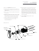
2 While holding the motor body, remove the bottom two
bolts that attach the motor to the pump casing (volute),
then slowly loosen the top two bolts. Allow the water to
drain from the bottom of the pump. When the water has
fi nished draining, remove the two top bolts. Remove the
motor straight out from the volute being careful of the
attached impeller.
Handle with care
The motor is heavy, and possibly hot,
do not drop it!
3 While holding the rotor very tightly by hand or a gloved
hand only, unscrew the impeller nut o the motor shaft by
turning it clockwise (i.e. opposite to most bolts and nuts).
Place the motor on its back, with the shaft up.
4 Remove the rotary part of the mechanical seal by gently
pulling it o the shaft. If it is too tight use two small fl at
bladed screwdrivers to gently pry it o the shaft by placing
the fl at side of the blades onto opposite sides of the
mechanical seal.
5 Remove the face plate from the motor by gently prying it
o of the motor housing extension, and carefully pulling it
straight up, avoiding any shaft contact.
6 Remove the stationary part of the seal by gently prying it o
the steel faceplate.
7 Remove any corrosion present on the stainless steel motor
shaft and face plate (especially the seal seat area) with a
non-metallic brush or scrub pad. Do not use a wire brush or
steel wool.
8 Remove any dust created during step #7 above and put a
few drops of non-petroleum lubricant around the face plate
where the stationary seat is to be installed.
9 Install the new stationary seal seat into the faceplate by
fi rmly pressing it down until it bottoms. The disk should
be clean. If needed, wipe it with alcohol and a soft lint
free cloth.
10 Replace the faceplate on the motor housing extension,
being careful to avoid shaft contact. This may need to be
gently tapped down until tight to the housing. Be sure to
check that the stainless steel plate is fl ush to the extender
plate face.
11 Install the special installation tool (180202-095) on the top
of the shaft making sure it is tight to the end of the shaft
and the fl ats fully engaged to protect the seal from sharp
edges during seal installation.
12 Apply a liberal amount of non-petroleum based lubricant
on the outside of the special plastic installation tool.
13 Wipe any excess lubricant o of the stationary silicon
carbide seal face with a lint free cloth and alcohol to ensure
the surface is clean.
14 Install the new rotating seal element and spring assembly
by gently pushing it (graphite ring fi rst) over the installa-
tion tool and onto the shaft until the graphite ring presses
tightly against the stationary seal seat. The seal spring may
be compressed slightly.