
Install Instructions


installation &
operating instructions
Armstrong
Compass H
2
Models
• Compass h 20-20 ci
• Compass h 20-20 ss
• Compass h 22-20 ssu
The Armstrong Compass H includes operating modes suitable
for systems with constant or variable flows, such as:
• Underfloor heating systems
• One-pipe (series) systems
• Two-pipe (parallel) systems
Armstrong Compass H circulators incorporate Armstrong
patented Design Envelope variable speed control technology
with an ecm motor, enabling optimum energy eciency and
occupant comfort, with built-in control algorithms that can
adapt to continuously changing system requirements.
The Armstrong Compass H features a user-friendly front-
mounted control panel (see section 5) and wiring box for ease
of installation.
2.2 advantages of installing an armstrong
compass h circulator
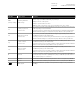
Nine dierent modes of operation to suit dierent
system requirements:
• Easily selectable from the front mounted display.
• Modes include sensorless demand-based control, Auto and
proportional pressure, fixed speed and constant pressure.
• Analog input for external variable speed control.
• Power consumption and flow rate clearly displayed.
Broad operating range, producing 20 feet of head or 20 USgpm
of flow, provides versatility to cover the performance of a wide
range of fixed speed or variable speed circulators.
• Flange to flange compatibility with existing Armstrong
circulators and many competing models.
Front mounted wiring box for ease of installation and service.
3.0 installation
3.1 extra electrical connector in the box
For your convenience Armstrong has supplied a PG7 electrical
strain relief connector in the box. It can replace the signal port
plug to secure an insulated signal cable with an outer diameter
between 3.0 to 6.5mm.
3.2 mounting
All servicing personnel should be equipped with proper person-
al protective equipment. Shut o the water supply, or isolate
the pump area. If valves have been installed, on the suction and
discharge sides of the pump, close them. If no valves have been
installed it may be necessary to drain the system. It is best to
leave the drain valve open while working on the system.
Install suction and discharge flanges on the pipe ends. The use
of Teflon tape sealer or a high quality thread sealant is recom-
mended. Install the Compass H with the flange gaskets. Flange
bolts should be tighten evenly to 60in/lbs of torque. To wire
the Compass H, follow section 4.0 in the Electrical Connection
section below.
Install the circulator where there will be sucient room for
inspection and service.
Note:
For future servicing, isolation flanges can be used in place of
standard flanges.
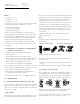
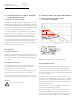
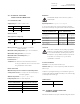
fig. 2 Mounting the Armstrong Compass H
Arrows on the pump housing indicate the liquid flow direction
through the pump.
1 Fit the two gaskets supplied when the pump is mounted in
the pipe.
2 Install the pump with the motor shaft horizontal (see fig. 2).
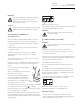
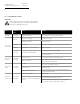
3.3 control box positions
The orientation of the display can be adjusted by removing four
screws that attach the motor to the pump housing (see fig.
3). Pump must be isolated from the system when making this
adjustments as this will open the system to the atmosphere.
fig. 3 Control box position (The inverted pump will work, just
reading the panel upside down is not recommended)
Ensure the gasket is intact and seated before evenly retighten-
ing the mounting screw to 4.5 - 5.5 lb/ft (6 - 7.5 Nm).
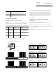
incorrect installations
correct installations
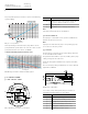
input
input
input
input
speed pressure curve
input
3195380
3195380
3195380
3195380
3195380