
Submittal Sheet

submittal
Compass H - Design Envelope
variable speed wet rotor circulators
armstrongfluidtechnology.com
armstrong fluid technology
established 1934
dubai
+971 4 887 6775
bangalore
+91 (0) 80 4906 3555
manchester
+44 (0) 8444 145 145
birmingham
+44 (0) 8444 145 145
buffalo
+1 716 693 8813
toronto
+1 416 755 2291
shanghai
+86 (0) 21 5237 0909
são paulo
+55 11 4785 1330
lyon
+33 (0) 420 102 625
+49 (0) 621 3999 9858
mannheim
2
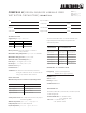
compass h performance curves
0 – 10vdc operation
pc1
pc2
pc3
pc4
iii
ii
head - ft.wg.
flow - usgpm
i
20
22
24
20 22
18
18
16
16
14
14
12
12
10
10
8
8
4
4
6
6
2
2
0
0
auto
pump starts from min. curve
pump max. curve
0 to 10 control (v)
speed
0
100%
12345678
910
pump o
Lights on the display indicate the Control mode selected.
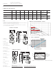
dimensions and weights
stainless steel* a b c d e f g
connection
type & size
weight
Compass h 20-20 ss flange 6.50 (165) 7.08 (180) 5.75 (146) 4.00 (102) 2.00 (50) 3.25 (80) 5.31 (135)
Flange – (2) ½" dia.
bolt holes
8.0 (3.6)
Compass h 20-20 ssu 6.00 (152) 7.08 (180) 5.75 (146) 4.00 (102) 2.00 (50) 1.25 (32) 5.31 (135) 1¼" Union
cast iron a b c d e f
g
connection
type & size
weight
Compass h 20-20 ci flange 6.50 (165) 7.08 (180) 5.75 (146) 4.00 (102) 2.00 (50) 3.25 (80) 5.31 (135)
Flange – (2) ½" dia.
bolt holes
8.0 (3.6)
note:
All dimensions are in inches (mm) and weights in lbs (kg).
*Certified <0.25 weighted average percent lead and complies with California Health and
Safety Code Section 116875 (commonly known as ab 1953).
** For open systems, it is recommended that the liquid temperature be less than 150°f
(65°c) to avoid precipitation of calcium.
e
f
d
b
c
a
g
(on center)
compass h flange
compass h union
e
f
d
b
c
a
g
pc4
pc
3
pc2
pc1
i
ii
iii
speed pressure curve
auto