
Install Instructions


installation &
operating instructions
Armstrong
Compass H
3
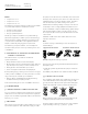
warning
The pumped liquid may be scalding hot and under
high pressure. Drain the system or close the
isolating valves on either side of the pump before
the screws are removed.
caution
After the position of the control box has been rotated,
refill the pump with system liquid before startup.
4.0 electrical connection
4.1 power supply
The electrical wiring must be installed strictly in accordance
with national electrical codes, local codes and regulations.
1 Electrical installation should be conducted by a qualified
electrician.
2 Always make sure electric power is disconnected before
wiring the circulator.
The motor is designed for 60 Hz, 1 phase, 115 volt power.
Wire shall be 14 to 16 gauge solid wire or 16 to 18 gauge
stranded wire.
To connect, loosen the screw from the wiring box cover and
remove the screw and cover.
Install a K" npt strain relief fitting (not included) for the power
wiring in the large access hole provided on the right side of
the box.
Insert the power wires through the fitting
and secure the wires.
Strip
3
/af" of insulation from the ends of the
three wires to be connected.
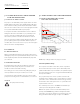
To insert the wires into the terminal strip,
press the terminal lever forward firmly.
Insert the stripped wire into the opening
and release the lever (see fig. 4). Tug on the
wire gently to ensure it is secured.
Connect the hot wire to terminal 'l1', the neutral wire to terminal
'l2/n', and the ground wire to terminal (see fig. 5).
Replace the wiring box cover and tighten screw, unless you plan
to use analog input (see section 4.2)
The pump is thermally protected so overload protection is not
necessary. All that is required is a fused plug or circuit breaker
in the power line. Electrical information can be found on the side
of the wiring box.
The electrical connections and protection must be carried out in
accordance with National Electric codes.
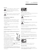
warning
The electrical supply must be disconnected when
wiring the circulator.
4.2 analog input (optional)
warning
Ensure circulator is disconnected. Wire must remain
isolated from power.
Wire shall be 18 to 24 gauge solid wire or stranded wire.
To connect, loosen the screw from the wiring box cover and
remove the screw and cover.
Install some form of strain relief connector (included in the box)
on the left side of the wiring compartment and tighten enough
so the wire does not slide when pulled.
Insert wires through the connector(s).
Strip
3
/af" of insulation from the ends of the two wires to be
connected.
To insert the wires into the analog input terminal strip, press
the terminal lever forward firmly. Insert the stripped wire into
the opening and release the lever (see fig. 4). Tug on the wire
gently to ensure it is secured.
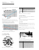
Connect the positive wire to terminal 'v' for voltage input con-
trol and the neutral wire to terminal 'c' (see fig. 6).
Replace the terminal box cover and tighten screw.
Analog input setting
The pump can be controlled by an external controller via
0-10Vdc. (See fig. 6 for how to install analog input wiring) En-
sure the analog input mode is selected.
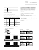
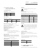
C V
fig. 6 Analog input connection 0-10vdc or 2-10vdc
L1 L2/N
fig. 5 Power supply connection
f
fig. 4 Terminal strip
1
2