
Brochure
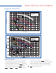
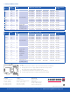

Composite Performance Charts
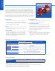
Typical Specification
Series S
Series H
Series S & H In-Line Circulators
0 10 20 30 40 50 60 70 80 90 100 110 120 130 140
(0) (0.63) (1.26) (1.89) (2.52) (3.15) (3.78) (4.41) (5.05) (5.68) (6.31) (6.94) (7.57) (8.20) (8.83)
150 160 170
(9.46) (10.09) (10.73)
Flow - USgpm (L/s)
Total Head - feet (m)
(12.1) 40
(10.7) 35
(9.1) 30
(7.6) 25
(6.1) 20
(4.6) 15
(3.0) 10
(1.5) 5
(0.0) 0
This chart is based on
1800 rpm, 60 Hz motors.
For 50 Hz motors
write for special capacity charts.
P
R
E
F
E
R
R
E
D
S
E
L
E
C
T
I
O
N
A
R
E
A
S-69
3"
S-57
3"
S-55
3"
S-46
3"
S-45
2½" & 3"
S-35
2"
S-25
¾", 1",
1¼" & 1½"
.
.
H-68
H-53
H-52
H-51
H-41
H-63
H-32
H-65
H-66
H-67
H-54
H-64
Furnish and install as shown on the plans, Armstrong S or H
Series Circulating Pump, designed for quiet operation and
guaranteed by the manufacturer for the intended applica-
tion. The pump shall have a capacity of USgpm (L/s),
handling (state liquid and temperature) against a total head of
ft (m). Pump shall be equipped with a hp (kW),
Volt, phase, Hz, 1800 rpm drip-proof
mounted motor. Pump shall be construction,
three-piece design featuring the Armstrong shaft and bearing
module which shall fit all models s-25 through s-57 and h-32
through h-54. Pump to be equipped with a water-tight,
long-life silicon carbide mechanical seal and be suitable for
psi (kPa) working pressure.