
User Guide
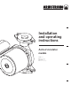


installation &
operating instructions
Astro 2
circulator models
5
The circulator shaft must always be in a horizontal position.
(The piping can be in a horizontal or vertical run.) Isolation
valves should be installed on the discharge and suction side of
the pump to facilitate service.
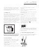
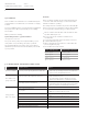
2.1 terminal box
Always install the circulator with the terminal box above or be-
side the motor. If the terminal box is under the motor as initially
mounted, remove the motor mounting screws and rotate the
motor to the proper position. (See example.)
Ensure the gasket is intact and seated before evenly retighten-
ing the mounting screw to 4.5 - 5.5 lb/ft (6 - 7.5 Nm). To ensure
the rotor still spins freely, temporarily remove the plug (located
in the middle of the nameplate), insert a flat head screwdriver
into the slot in the end of the rotor shaft and turn.
Retighten the plug to 1.5 - 2 lb/ft (2 -2.7 Nm). Ensure no water
leak at all sealing contacts.
Do not hang items or articles of clothing on the pump as air
must be able to circulate freely through the motor. Do not
operate the circulator without the motor plug installed.
2.2 electrical wiring
The electrical wiring must be installed strictly in accordance
with national electrical codes, local codes and regulations.
1
Electrical installation should be conducted by a
qualified electrician.
2
Always make sure electric power is disconnected before
wiring the circulator.
The motor is designed for 60 Hz, 1 phase, 115 or 230 volt power.
Wire shall be 14 to 16 gauge solid wire or 16 to 18 gauge
stranded wire.
To wire, loosen the screws from the terminal box cover and
remove the screws and cover.
Install constractors choice of strain relief into ½" npt threaded
access kit (not provided).
Insert wires through the strain relief connector and into the
terminal box.
Strip ³/af" of insulation from the ends of the three wires to
be connected.
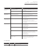
To insert the wires into the terminal strip, press down firmly on
the terminal lever. Insert the stripped wire into the opening and
release the lever. Tug on the wire gently to ensure it is secured.
Connect the hot wire to terminal 'l', the neutral wire to terminal
'n', and the ground wire to terminal
f
.
Tighten the terminal box cover.
The motor is thermally protected so overload protection is not
necessary. All that is required is a fused plug or circuit breaker
in the power line. Electrical information can be found on the
nameplate of the motor.
3.0 check valve removal (optional)
Using a pair of needle-nose pliers, grip one of the flat wings of
the check valve and gently pull the valve out vertically.
f
plug
1
2
3