
Manual

40
NOTE:
The helmet mount provides two positions for the user to position the MUNVM. The ipped
down position allows the user to position the MUNVM directly in front of the eyes. The helmet
mount also allows the user to rotate the MUNVM to a ipped up position when the MUNVM is
not needed for immediate use. Both the ipped down and the ipped up positions have a posi-
tive stop which assures the user that the MUNVM is in the correct position.
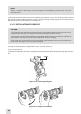
Perform the following procedures for helmet mounted operation.
(1) Ensure that the battery are installed per paragraph 3.3.2.
(2) Don the helmet mount per instructions in paragraph 3.3.8.
(3) Place the monocular in the socket of the helmet mount.
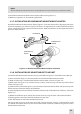
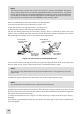
Set your eye relief by depressing the side buttons (or press down on side lever on metal mount) (see
Figure 3-20) and carefully move the monocular fore or aft until the eyecup comfortably seals around
the eye. Readjust the helmet straps as required for vertical adjustment.
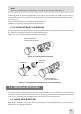
(4) Turn power switch to ON. Adjust the tilt by using the tilt adjustment lock knob (or tilt adjustment
lever on metal mount) (Figure 3-20) until you obtain a comfortable viewing angle.
NOTE:
The sharpest image will be observed only when the objective lens and eyepiece lens are prop-
erly focused.
(5) Rotate the diopter adjustment for the clearest view of the image intensier screen.
NOTE:
Any readjustment of eye relief requires readjustment of the diopter.
(6) Adjust the eye relief distance by depressing the side buttons (Figure 3-20) (or press down on side
lever on metal mount) and sliding monocular fore or aft to obtain a full eld-of-view of the image. Reset
the diopter adjustment for best image.
(7) Adjust the objective lens focus (Figure 3-1) while observing an object until the sharpest image is
obtained.
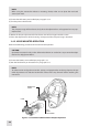
(8) To ip up, grasp the helmet tilt and ip-up assembly and rotate upward and rearward until the latch
is rmly engaged.
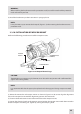
PLASTIC MOUNT
TILT ADJUSTMENT
LOCK KNOB
SOCKET
SIDE
BUTTONS (2 EA)
(FORE-AND-AFT
ADJUSTMENT)
METAL MOUNT
TILT ADJUSTMENT
LEVER
SOCKET
SIDE LEVER
(FORE-AND-AFT
ADJUSTMENT)
Figure 3-20. Tilt and Flip-up Assembly Mechanisms