
User guide

29
3.2 CONTROLS AND DISPLAY INDICATIONS
3.2.1 CIPHER CONTROLS
CAUTION:
DO NOT force the equipment controls past their stopping points.
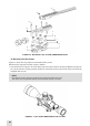
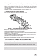
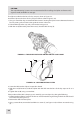
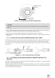
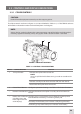
The Cipher controls are shown in Figures 3-19, 3-20 and dened in Tables 3-1, 3-2. The ITEM NO. columns
of the tables indicate the number used to identify items in the gures.
NOTE:
Various display symbols indicating the current operating state of the Cipher are displayed per-
manently, appear momentarily, or may only appear when a certain function is activated.
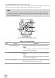
TABLE 31. CONTROLS AND INDICATORS
ITEM NO. CONTROL/INDICATOR FUNCTION
1 Turn-pull Switch Activates the Cipher when turned ON.
NOTE:
You must pull the knob before turning in order to use either ON
or STB.
Activates standby mode when turned to STB (see note above).
Deactivates the Cipher when turned OFF.
2 Control Panel Buttons Congures operational settings. See Table 3-2 for button functions.
— Remote Control Button Activates/deactivates the Cipher in standby when held down/re-
leased.
— Battery Status Indicator
(a battery icon in the
lower, right-hand area
of the display)
The light gray bar in the battery icon indicates the current power
level of the internal battery, or remaining battery life.
The totally shaded battery icon indicates a fully charged battery.
The ashing transparent battery icon indicates a low battery.
1
2
FIGURE 319. CIPHER CONTROLS