
User guide

21
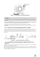
objective lens.
5. Ax the Cipher to the rail by locking the cam lever (A, see Figure 3-3).
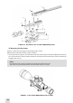
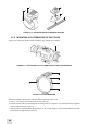
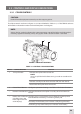
FIGURE 34. MOUNT. TOP VIEW
C
B
LOCKED POSITION UNLOCK POSITION
A
6. Verify that the clamping device is rmly holding the Cipher. If necessary, adjust the clamping device
as detailed in Part 3.1.3 (Clamping Device Adjustment).
3.1.3 CLAMPING DEVICE ADJUSTMENT
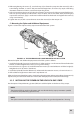
Adjust the mount clamping device as follows (refer to Figure 3-4):
1. Unlock the clamping device and remove the Cipher from the weapon.
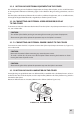
2. To tighten/loosen the clamping device (B), push the cam (C) towards the arrow (which will cause the
nut (A) to slide out of its hole) and turn the nut (A) CW/CCW respectively, in one-two increments (see
note below). Much like when the cam (C) is released, backward-moving springs will cause the nut (A)
to slide back into its hole.
NOTE:
The eight-sided nut of the clamping device will only t into its hole if turned in one of the dis-
crete positions using increments equal to 360°/8.
3. Verify that the adjusted clamping device is securely holding the Cipher.
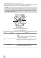
FIGURE 35. MOUNT. UNDERSIDE VIEW
LOCKED POSITION UNLOCK POSITION
A
B
C
3.1.4 INSTALLING THE CIPHER ON A WEAPON USING THE OPTIONAL FSRS
SYSTEM
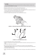
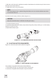
The FSRS (Front Scope Rail System) is delivered ready-assembled. The components of the FSRS system
are shown in Figure 3-7.
A. Dismantling the FSRS System
Dismantle the FSRS system as follows (see Figure 3-7):
1. Loosen the nuts (D); remove the extension mount (E) from the bridge (B).
2. Unscrew the screws (C) and remove the bridge (B) from the mount (H).
3. Unscrew the screws (F) and remove the clamps (G).