
Specifications


Standard Initialization Sequence for Hercules Microcontrollers
www.ti.com
NOTE: The FMPLL takes (127 + 1024*NR) oscillator cycles to acquire lock to the target frequency,
hence it is recommended to configure the FMPLL(s) and enable them as soon as possible in
the device initialization.
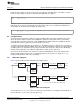
2.2.2 FMPLL Slip Detector
The FMPLL macro has a slip detector circuit that compares the OSCIN to the VCOCLK and flags any
single-cycle slips. The application can choose the response to a PLL slip indication from among three
choices: do nothing, cause a system reset, or bypass the FMPLL such that the OSCIN frequency itself is
supplied as the output from the FMPLL macro. There is also a slip filter circuit that can be enabled by the
application, which allows the application to require the PLL to detect a slip condition for two or more
consecutive cycles before the slip is actually indicated to the system.
2.2.3 FMPLL Modulation
The FMPLL allows the application to enable modulation (insertion of controlled jitter). The modulation
characteristics are configured by the PLLCTL2 control register. The modulation option is only available for
the main FMPLL.
2.2.4 FMPLL Configuration
The FMPLL1 has two control registers located within the System module on the Hercules microcontrollers:
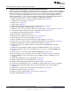
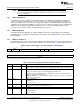
PLLCTL1 and PLLCTL2. PLL control register 1 (PLLCTL1) is shown in Figure 4 and described in Table 1.
Figure 4. PLL Control Register 1 (PLLCTL1) Address = 0xFFFFFF70
31 30 29 28 24 23 22 21 16
MASK_
ROS PLLDIV[4:0] ROF RSVD REFCLKDIV[5:0]
SLIP[1:0]
R/WP-0 R/WP-01 R/WP-01111 R/WP-0 R-0 R/WP-000010
15 0
PLLMUL[15:0]
R/WP-0x5F00
LEGEND: R = Read in all modes; WP = Write in priviledged mode only; -n = value after reset
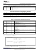
Table 1. PLL Control Register (PLLCTL1) Field Descriptions
Bit Field Value Description
31 ROS Reset-on slip selects whether a PLL slip condition causes a system reset or not.
ROS = 1 causes a system reset when a PLL slip is flagged and the slip detection is not masked.
30-29 MASK_SLIP Mark slip allows the application to ignore a slip indicated by the PLL.
MASK_SLIP = 10 ignores a PLL slip condition flagged by the FMPLL macro.
Writing any other value to MASK_SLIP causes the FMPLL to be bypassed so that the OSCIN is
used as the output from the FMPLL macro.
NOTE: If the ROS bit is also ‘1’ when the FMPLL is bypassed, then a system reset occurs and the
FMPLL output is not bypassed.
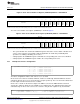
28-24 PLLDIV Defines the R-divider.
R = PLLDIV + 1
f
PLLCLK
= f
post-ODCLK
/ R
23 ROF Reset-on-oscillator-fail controls the response to an oscillator failure detected by the clock monitor
and is not relevant to the PLL configuration discussion.
22 Reserved 0 Reserved
21-16 REFCLKDIV Defines the NR-divider
NR = REFCLKDIV + 1
f
INTCLK
= f
CLKIN
/ NR
6
Initialization of Hercules™ ARM
®
Cortex™-R4F Microcontrollers SPNA106– September 2011
Submit Documentation Feedback
Copyright © 2011, Texas Instruments Incorporated