
Specifications


Standard Initialization Sequence for Hercules Microcontrollers
www.ti.com
2 Standard Initialization Sequence for Hercules Microcontrollers
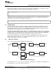
A basic sequence for initialization and configuration of the key features on a Hercules MCU is summarized
below and detailed in the following sections. Some parts of the initialization sequence are not mandatory.
Applications that are non-safety-critical can choose to not use the ECC feature for Flash and RAM
accesses, for example. Each application must also have its specific exception handling scheme: reset
handler, abort handler, etc. The code generated using nowGen includes template handling routines for
each exception. These routines need to be modified as required by the application.
1. Initialize stack pointer for the supervisor (default) operating mode, Section 2.1
2. Configure PLL control registers, Section 2.2
3. Enable the PLLs, Section 2.3
4. Trim the LPO, Section 2.4
5. Enable the floating-point Unit (FPU) inside the Cortex-R4F CPU, Section 2.5
6. Initialize the CPU registers and FPU registers, Section 2.6
7. Handle the cause of reset to determine whether to continue with the start-up sequence, Section 2.7
8. Set up Flash module for required wait states and pipelined mode, Section 2.8
9. Set up Flash bank and pump power modes, Section 2.9
10. Wait for main PLL output to become valid
11. Map device clock domains to desired clock sources, Section 2.10
12. Run the built-in self-test for the CPU (LBIST), Section 2.11
13. Release peripherals from reset and enable clocks to all peripherals, Section 2.12
14. Start self-tests on all device memories using programmable built-in self-test (PBIST), Section 2.13
15. Enable the floating-point Unit (FPU) inside the Cortex-R4F CPU, Section 2.5
16. Enable the response mechanism to ECC errors inside flash and TCRAM interface modules,
Section 2.14
17. Enable CPU Event Signaling and ECC checking on ATCM and BTCM accesses, Section 2.15
18. Run eFuse controller start-up checks including self-test on the eFuse controller SECDED logic,
Section 2.17
19. Run the self-test on the Flash module embedded SECDED logic, Section 2.18
20. Check whether the eFuse controller self-test has completed; wait here if it has not completed
21. Check if all RAMs have passed the memory self-test (PBIST); wait here if PBIST has not yet
completed
22. Perform auto-initialization for all on-chip SRAMs, Section 2.19
23. Initialize stack pointers for all operating modes, Section 2.20
24. Configure IRQ / FIQ interrupt priorities for all interrupt channels, Section 2.21.2
25. Check if the auto-initialization process for all RAMs is completed; wait here if it has not completed
26. Program Vectored Interrupt Manager memory to map all interrupt service routine addresses,
Section 2.21
27. Enable CPU’s dedicated vectored interrupt controller (VIC) port, Section 2.22
28. Enable the desired interrupts, Section 2.21.3
29. Initialize copy table, global variables, and constructors, Section 2.24
30. Call the main application, Section 2.25
4
Initialization of Hercules™ ARM
®
Cortex™-R4F Microcontrollers SPNA106– September 2011
Submit Documentation Feedback
Copyright © 2011, Texas Instruments Incorporated