
Specifications


Standard Initialization Sequence for Hercules Microcontrollers
www.ti.com
2.21.2 Configure Interrupts to be Fast Interrupts or Normal Interrupts
Two registers in the VIM module allow each of the interrupts to be assigned to either the fast interrupt
(FIQ) queue, or the normal interrupt queue (IRQ).
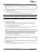
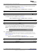
The FIQ/IRQ control register 0 (FIRQPR0) is shown in Figure 26.
Figure 26. FIQ/IRQ Control Register 0 (FIRQPR0) Address = 0xFFFFFE10
31 16
FIRQPR[31:16]
R/WP:0
15 2 1 0
FIRQPR[15:0] Reserved
R/WP:0
LEGEND: R = Read in all modes; WP = Write in priviledged mode; -n = value after reset
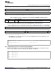
The FIQ/IRQ control register 1 (FIRQPR1) is shown in Figure 27.
Figure 27. FIQ/IRQ Control Register 1 (FIRQPR1) Address = 0xFFFFFE14
31 16
FIRQPR[63:48]
R/WP-0
15 0
FIRQPR[47:32]
R/WP-0
LEGEND: R = Read in all modes; WP = Write in priviledged mode; -n = value after reset
There are similar registers FIRQPR2 at 0xFFFFFE18 and FIRQPR3 at 0xFFFFFE1C for interrupt
channels up to 128. Setting any bit in these registers makes the corresponding interrupt request an FIQ
interrupt. As shown, the interrupt requests 0 and 1 are always FIQ. All others are IRQ interrupts by
default.
NOTE: An interrupt request mapped to FIQ cannot use the CPU’s VIC port.
2.21.3 Enabling Interrupts
Control registers in the VIM module allow each interrupt request to be enabled or disabled. There are
registers to enable all 128 channels. The registers to enable the first 64 interrupt channels are shown in
Figure 28 and Figure 29.
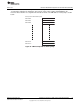
The interrupt enable set register 0 (REQENASET0) is shown in Figure 28.
Figure 28. Interrupt Enable Set Register 0 (REQENASET0) Address = 0xFFFFFE30
31 16
REQENASET[31:16]
R/WP:0
15 2 1 0
REQENASET[15:0] Reserved
R/WP:0
LEGEND: R = Read in all modes; WP = Write in priviledged mode; -n = value after reset
30
Initialization of Hercules™ ARM
®
Cortex™-R4F Microcontrollers SPNA106– September 2011
Submit Documentation Feedback
Copyright © 2011, Texas Instruments Incorporated