
Specifications


www.ti.com
Standard Initialization Sequence for Hercules Microcontrollers
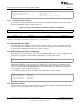
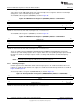
Figure 23. Memory Self-Test / Initialization Control Register (MSIENA) Address = 0xFFFFFF60
31 16
MSIENA[31:16]
R/WP-0
15 0
MSIENA[15:0]
R/WP-0
LEGEND: R = Read in all modes; WP = Write in priviledged mode; -n = value after reset
Table 14. Memory Self-Test / Initialization Control Register (MSIENA) Field Descriptions
Bit Field Value Description
31-0 MSIENA Each bit of MSIENA refers to a single SRAM module on the microcontroller. For the on-chip SRAM
mapping to the initialization channel number, see the specific part's datasheet.
The memory self-test / initialization status register (MSTCGSTAT) is shown in Figure 24.
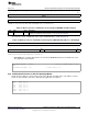
Figure 24. Memory Self-Test / Initialization Status Register (MSTCGSTAT) Address = 0xFFFFFF68
31 16
Reserved
R-0
15 9 8 7 1 0
MINI MST
Reserved Reserved
DONE DONE
R-0 R/WP-0 R-0 R/WP-0
LEGEND: R = Read in all modes; WP = Write in priviledged mode; -n = value after reset
• MINI DONE gets set when all memories selected via the MSIENA field have been initialized to zeros.
The application can poll this bit.
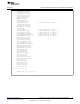
systemREG1->MSIENA = 0xE57F; // Select all SRAMs capable of auto-
init
systemREG1->MINITGCR = 0xA; // Enable memory init
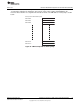
2.20 Initialize Stack Pointers for All CPU Operating Modes
Define the base addresses for the stacks used for the different operating modes. The addresses listed
below are only examples and can be defined by the application as required.
user: .word 0x08001000
svc: .word 0x08002000
sys: .word 0x08003000
fiq: .word 0x08004000
irq: .word 0x08005000
abort: .word 0x08006000
undef .word 0x08007000
25
SPNA106– September 2011 Initialization of Hercules™ ARM
®
Cortex™-R4F Microcontrollers
Submit Documentation Feedback
Copyright © 2011, Texas Instruments Incorporated