
Specifications


Standard Initialization Sequence for Hercules Microcontrollers
www.ti.com
systemREG1->CLKCNTL |= 0x00000000U ; // VCLK2 = HCLK/1
temp = systemREG1->CLKCNTL; // dummy read to cause delay
systemREG1->CLKCNTL |= 0x00010000U; // VCLK = HCLK/2
| (0U); // Use FMPLL as source for RTI1CLK
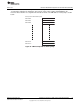
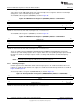
2.10.4 Configuring VCLK3 Frequency
The VCLK3 clock signal is divided down from the HCLK clock signal. This divider is in the clock control
register 2 (CLK2CNTL), which is shown in Figure 21.
Figure 21. Clock Control Register 2 (CLK2CNTL) Address = 0xFFFFE13C
31 16
Reserved
R-0
15 12 11 8 7 4 3 0
Reserved VCLK4R[3:0] Reserved VCLK3R[3:0]
R-0 R/WP-0001 R-0 R/WP-0001
LEGEND: R = Read in all modes; WP = Write in priviledged mode; -n = value after reset
2.11 Run CPU Self-Test (LBIST)
For information on the configuration and execution of the CPU self-test, see the specific part's technical
reference manual. The CPU will be reset once the self-test is completed. The reset handler routine can
resume the device initialization from the next step in the sequence.
2.12 Release Reset and Clocks to Peripherals
The peripherals are kept under reset, and need to be explicitly brought out of reset by the application. This
can be done by setting the Peripheral Enable (PENA) bit of the clock control register.
systemREG1->CLKCNTL |= 0x00000100U; // Release peripheral reset
The clocks to the peripheral modules are also disabled upon any system reset and need to be explicitly
enabled by the application. This can be done by setting the bits corresponding to the peripheral select
quadrant occupied by the peripheral module in the PCR module registers for clearing the power down
states of peripheral modules (PSPWRDWNCLRx). For information on the peripheral select quadrants for
each peripheral, see the specific part's datasheet.
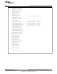
In the following example, the clocks to all implemented peripherals are being enabled.
pcrREG->PSPWRDWNCLR0 = 0xFFFFFFFFU;
pcrREG->PSPWRDWNCLR0 = 0xFFFFFFFFU;
pcrREG->PSPWRDWNCLR0 = 0xFFFFFFFFU;
pcrREG->PSPWRDWNCLR0 = 0xFFFFFFFFU;
2.13 Memories’ Self-Test
For information on executing the self-test on the on-chip memories using the programmable BIST (PBIST)
engine, see the specific part's technical reference manual.
22
Initialization of Hercules™ ARM
®
Cortex™-R4F Microcontrollers SPNA106– September 2011
Submit Documentation Feedback
Copyright © 2011, Texas Instruments Incorporated