
Specifications


www.ti.com
Standard Initialization Sequence for Hercules Microcontrollers
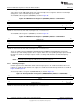
The asynchronous clock source register (VCLKASRC) is shown in Figure 19.
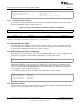
Figure 19. RTI Clock Source Register (RCLKSRC) Address = 0xFFFFFF50
31 16
Reserved
R-0
15 12 11 8 7 4 3 0
Reserved RTIDIV[1:0] Reserved RTI1SRC[3:0]
R-0 R/WP-01 R-0 R/WP-1001
LEGEND: R = Read in all modes; WP = Write in priviledged mode; -n = value after reset
• RTI1SRC field defines the clock source used for the RTI1CLK domain. This domain is mapped to
VCLK by default.
• If the clock source for RTI1CLK is selected to be something other than VCLK, then the RTI1CLK
frequency must be at least 1/3rd of the VCLK frequency. This can be achieved by using the RTI2DIV
field, which defines the divider values used to divide down the clock source selected for RTI1CLK.
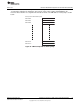
2.10.2 Example Clock Domain Mapping
systemREG1->GHVSRC = (0U << 24U) // Use main oscillator as wake up source for GHV CLK
| (0U << 16U) // Use main oscillator for HV CLK when GCLK is off
| (1U); // Use FMPLL as current source for GHV CLK
systemREG1->VCLKASRC = (6U << 8U) // Use second PLL output for FlexRay bit timing
| (0U); // Use main oscillator for DCANx bit timings
systemREG1->RCLKSRC = (1U << 8U) // Set the RTI1CLK divider to divide-by-2
| (0U); // Use FMPLL as source for RTI1CLK
2.10.3 Configuring VCLK and VCLK2 Frequencies
The VCLK and VCLK2 clock signals are divided down from the HCLK clock signal. These are independent
dividers that can be configured via the system module Clock Control Register (CLKCNTL).
The peripheral clock control register (CLKCNTL) is shown in Figure 20.
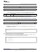
Figure 20. Peripheral Clock Control Register (CLKCNTL) Address = 0xFFFFFFD0
31 28 27 24 23 20 19 16
Reserved VCLK2R Reserved VCLKR
R-0 R/WP-0001 R-0 R/WP-0001
15 9 8 7 0
Reserved PENA Reserved
R-0 R/WP-0 R-0
LEGEND: R = Read in all modes; WP = Write in priviledged mode; -n = value after reset
• VCLK2R defines the divide ratio between HCLK and VCLK2.
• VCLKR defines the divide ratio between HCLK and VCLK.
– VCLK2 and VCLK can be from HCLK/1 to HCLK/16
NOTE:
• VCLK2 frequency must also be an integer multiple of VCLK frequency.
• There must be some delay between configuring the divide ratios for VCLK2 and VCLK.
21
SPNA106– September 2011 Initialization of Hercules™ ARM
®
Cortex™-R4F Microcontrollers
Submit Documentation Feedback
Copyright © 2011, Texas Instruments Incorporated