
Specifications


Standard Initialization Sequence for Hercules Microcontrollers
www.ti.com
2.9 Configure Flash Bank and Pump Power Modes
The Flash banks and pump used on the Hercules series microcontrollers support three different operating
modes to optimize power consumption.
• Active mode
– Flash bank sense amplifiers and sense reference are enabled
– All circuits of Flash charge pump are enabled
• Standby mode (only for Flash banks)
– Flash bank sense reference is enabled but sense amplifiers are disabled
• Sleep Mode
– Flash bank sense amplifiers and sense reference are disabled
– All circuits of Flash charge pump are disabled
The Flash banks and charge pump are in the active state by default and after any system reset. The Flash
module allows the application to configure “fall back” power states for the Flash banks and charge pump.
The Flash banks and pump automatically switch the power mode to the selected fall back state when
there is no access to the Flash banks detected within a user-configurable time.
The Flash module also contains special timers to automatically sequence the Flash banks and pump
between the active and the selected fall-back states. A read access to any Flash bank which is in a
non-active power state will “wake up” both the selected bank and the charge pump to active power state.
Programming and erase operations are only allowed on banks in active state.
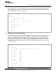
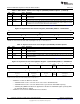
The Flash module register that controls the Flash banks’ power states is shown in Figure 12.
Figure 12. Flash Bank Fall-Back Control Register (FBFALLBACK) Address = 0xFFF87040
31 16
Reserved
R-0
15 8 7 6 5 4 3 2 1 0
BANKPWR3 BANKPWR2 BANKPWR1 BANKPWR3
Reserved
[1:0] [1:0] [1:0] [1:0]
R/WP-0xF R/WP-11 R/WP-11 R/WP-11 R/WP-11
LEGEND: R = Read in all modes; WP = Write in priviledged mode only; -n = value after reset
16
Initialization of Hercules™ ARM
®
Cortex™-R4F Microcontrollers SPNA106– September 2011
Submit Documentation Feedback
Copyright © 2011, Texas Instruments Incorporated