
Specifications


www.ti.com
Standard Initialization Sequence for Hercules Microcontrollers
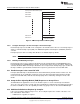
The clock sources for the VCLKA3 and VCLKA4 domains are selected via the Peripheral Asynchronous
Clock Configuration 1 Register (VCLKACON1).
The clock source for the RTI1CLK domain is selected via the RTI Clock Source Register (RCLKSRC).
2.15.2 Example Clock Domain Mapping
systemREG1->GHVSRC = (0U << 24U) // Use main oscillator as wake up source for GHV CLK
| (0U << 16U) // Use main oscillator for HV CLK when GCLK is off
| (1U); // Use FMPLL as current source for GHV CLK
systemREG1->VCLKASRC = (6U << 8U) // Use second PLL output for FlexRay bit timing
| (0U); // Use main oscillator for DCANx bit timings
systemREG1->RCLKSRC = (1U << 8U) // Set the RTI1CLK divider to divide-by-2
| (0U); // Use FMPLL as source for RTI1CLK
2.15.3 Configuring VCLK , VCLK2 and VCLK3 Frequencies
The VCLK and VCLK2 clock signals are divided down from the HCLK clock signal. These are independent
dividers that can be configured via the system module clock control register (CLKCNTL).
NOTE:
• VCLK2 frequency must also be an integer multiple of VCLK frequency.
• There must be some delay between configuring the divide ratios for VCLK2 and VCLK.
The VCLK3 clock signal is also divided down from the HCLK clock signal. This divider is in the Clock
Control Register 2 (CLK2CNTL).
2.16 Run a Diagnostic Check on CPU Self-Test Controller (STC)
This involves running one CPU self-test interval in STC check mode. The STC self-check mode causes a
stuck-at-0 fault to be introduced inside one of the two CPUs for there to be an STC failure. If no STC
failure is indicated, this would mean that the STC is not capable of detecting a fault inside the CPU, and
device operation is not reliable. For information on the configuration and execution of the STC self-test,
see the device-specific technical reference manual. The CPU will be reset once the STC self-test is
completed. The reset handler routine can resume the device initialization from the next step in the
sequence.
2.17 Run CPU Self-Test (LBIST)
For information on the configuration and execution of the CPU self-test, see the device-specific technical
reference manual. The CPU will be reset once the self-test is completed. The reset handler routine can
resume the device initialization from the next step in the sequence.
2.18 Run a Diagnostic Check on the CPU Compare Module (CCM-R4F)
The CCM-R4F compares the dual Cortex-R4F CPU outputs on each CPU clock cycle. Any mismatch is
indicated as an ESM group2 error. This ensures that the two CPUs are indeed operating in a lock-step
mode. The CCM-R4F module also allows the application to test the different error conditions using built-in
self-test routines. For information on how to configure the CCM-R4F in a self-test mode, see the device-
specific technical reference manual.
11
SPNA106D–May 2013 Initialization of Hercules™ ARM
®
Cortex™-R4F Microcontrollers
Submit Documentation Feedback
Copyright © 2013, Texas Instruments Incorporated