
User guide


Instrumentation Trace Macrocell Unit
ARM DDI 0337I Copyright © 2005-2008, 2010 ARM Limited. All rights reserved. 9-4
ID072410 Non-Confidential
9.3 ITM programmers model
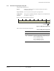
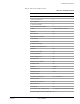
Table 9-1 shows the ITM registers. Depending on the implementation of your processor, the
ITM registers might not be present. Any register that is configured as not present reads as zero.
Note
• You must enable TRCENA of the Debug Exception and Monitor Control Register before
you program or use the ITM.
• If the ITM stream requires synchronization packets, you must configure the
synchronization packet rate in the DWT.
Note
ITM registers are fully accessible in privileged mode. In user mode, all registers can be read,
but only the Stimulus Registers and Trace Enable Registers can be written, and only when the
corresponding Trace Privilege Register bit is set. Invalid user mode writes to the ITM registers
are discarded.
The following sections describes the ITM registers whose implementation is specific to this
processor. Other registers are described in the ARMv7-M Architectural Reference Manual.
Table 9-1 ITM register summary
Address Name Type Reset Description
0xE0000000
-
0xE000007C
ITM_STIM0-
ITM_STIM31
RW - Stimulus Port Registers 0-31
0xE0000E00
ITM_TER RW
0x00000000
Trace Enable Register
0xE0000E40
ITM_TPR RW
0x00000000
ITM Trace Privilege Register, ITM_TPR on page 9-5
0xE0000E80
ITM_TCR RW
0x00000000
Trace Control Register
0xE0000FD0
PID4 RO
0x00000004
Peripheral Identification registers
0xE0000FD4
PID5 RO
0x00000000
0xE0000FD8
PID6 RO
0x00000000
0xE0000FDC
PID7 RO
0x00000000
0xE0000FE0
PID0 RO
0x00000001
0xE0000FE4
PID1 RO
0x000000B0
0xE0000FE8
PID2 RO
0x0000003B
0xE0000FEC
PID3 RO
0x00000000
0xE0000FF0
CID0 RO
0x0000000D
Component Identification registers
0xE0000FF4
CID1 RO
0x000000E0
0xE0000FF8
CID2 RO
0x00000005
0xE0000FFC
CID3 RO
0x000000B1