
User guide


Debug
ARM DDI 0337I Copyright © 2005-2008, 2010 ARM Limited. All rights reserved. 7-3
ID072410 Non-Confidential
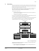
2. Follow the pointers in that Cortex-M3 ROM table:
a. System Control Space (SCS)
b. Breakpoint unit (BPU)
c. Data watchpoint unit (DWT).
See Table 7-2 on page 7-4 for more information.
When a debugger identifies the SCS from its CoreSight identification, it can identify the
processor and its revision number from the CPUID register in the SCS at address
0xE000ED00
.
A debugger cannot rely on the Cortex-M3 ROM table being the first ROM table encountered.
One or more system ROM tables are required between the access port and the Cortex-M3 ROM
table if other CoreSight components are in the system. If a system ROM table is present, this
can include a unique identifier for the implementation.
7.1.1 Cortex-M3 ROM table identification and entries
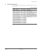
Table 7-1 shows the ROM table identification registers and values for debugger detection. This
permits debuggers to identify the processor and its debug capabilities.
These are the default values for the Peripheral ID registers if the ROM table has not been configured at
implementation. Your implementation might use these registers to identify the manufacturer and part
number for the device.
The Component ID registers identify this as a CoreSight ROM table.
Note
The Cortex-M3 ROM table only supports word size transactions.
Table 7-1 Cortex-M3 ROM table identification values
Address Register Value Description
0xE00FFFD0
Peripheral ID4
0x00000004
Component and Peripheral ID register formats in the
ARMv7-M Architectural Reference Manual
0xE00FFFD4
Peripheral ID5
0x00000000
0xE00FFFD8
Peripheral ID6
0x00000000
0xE00FFFDC
Peripheral ID7
0x00000000
0xE00FFFE0
Peripheral ID0
0x000000C3
0xE00FFFE4
Peripheral ID1
0x000000B4
0xE00FFFE8
Peripheral ID2
0x0000000B
0xE00FFFEC
Peripheral ID3
0x00000000
0xE00FFFF0
Component ID0
0x0000000D
0xE00FFFF4
Component ID1
0x00000010
0xE00FFFF8
Component ID2
0x00000005
0xE00FFFFC
Component ID3
0x000000B1