
User guide


System Control
ARM DDI 0337I Copyright © 2005-2008, 2010 ARM Limited. All rights reserved. 4-6
ID072410 Non-Confidential
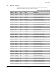
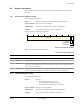
Figure 4-2 shows the CPUID bit assignments.
Figure 4-2 CPUID bit assignments
Table 4-3 shows the CPUID bit assignments.
4.3.3 Auxiliary Fault Status Register, AFSR
The AFSR characteristics are:
Purpose Specifies additional system fault information to software.
Usage Constraints The AFSR flags map directly onto the AUXFAULT inputs of the
processor, and a single-cycle high level on an external pin causes the
corresponding AFSR bit to become latched as one. The bit can only be
cleared by writing a one to the corresponding AFSR bit.
When an AFSR bit is written or latched as one, an exception does not
occur. To make use of AUXFAULT input signals, software must poll the
AFSR.
Configurations This register is available in all processor configurations.
Attributes See the register summary in Table 4-1 on page 4-3.
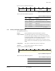
Figure 4-3 shows the AFSR bit assignments.
Figure 4-3 AFSR bit assignments
Table 4-4 shows the AFSR bit assignments.
31 16 15 4 3 0
IMPLEMENTER
REVISIONPARTNO
24 23 20 19
VARIANT (Constant)
Table 4-3 CPUID bit assignments
Bits NAME Function
[31:24] IMPLEMENTER Indicates implementer:
0x41
= ARM
[23:20] VARIANT Indicates processor revision:
0x2
= Revision 2
[19:16] (Constant) Reads as
0xF
[15:4] PARTNO Indicates part number:
0xC23
= Cortex-M3
[3:0] REVISION Indicates patch release:
0x1
= Patch 1.
AUXFAULT
31 0
Table 4-4 AFSR bit assignments
Bits Name Function
[31:0] AUXFAULT Latched version of the AUXFAULT inputs.