
User guide


Trace Port Interface Unit
ARM DDI 0337I Copyright © 2005-2008, 2010 ARM Limited. All rights reserved. 11-10
ID072410 Non-Confidential
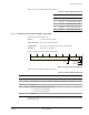
Table 11-7 shows the ITATBCTR2 bit assignments.
11.3.7 Integration ITM Data
The Integration ITM Data characteristics are:
Purpose Trace data integration testing.
Usage constraints You must set bit [1] of TPIU_ITCTRL to use this register. See Integration
Mode Control, TPIU_ITCTRL on page 11-11.
Configurations This register is available in all processor configurations.
Attributes See Table 11-1 on page 11-5.
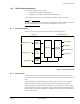
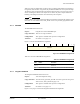
Figure 11-8 shows the Integration ITM Data bit assignments.
Figure 11-8 Integration ITM Data bit assignments
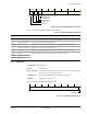
Table 11-8 shows the Integration ITM Data bit assignments.
Table 11-7 ITATBCTR2 bit assignments
Bits Name Function
[31:1] - Reserved
[0] ATREADY1, ATREADY2 This bit sets the value of both the ETM and ITM ATREADY
outputs, if the TPIU is in integration test mode.
31 30 29 28 27 26 25 24 23 16 15 8 7 0
ITM data 2 ITM data 1 ITM data 0
ETM byte count
ETM ATVALID input
ITM byte count
ITM ATVALID input
Reserved
Table 11-8 Integration ITM Data bit assignments
Bits Name Function
[31:30] - Reserved
[29]
ITM ATVALID input Returns the value of the ITM ATVALID signal.
[28:27]
ITM byte count Number of bytes of ITM trace data since last read of Integration ITM Data Register.
[26]
ETM ATVALID input Returns the value of the ETM ATVALID signal.
[25:24]
ETM byte count Number of bytes of ETM trace data since last read of Integration ETM Data Register.
[23:16]
ITM data 2
ITM trace data. The TPIU discards this data when the register is read.
[15:8]
ITM data 1
[7:0]
ITM data 0