
User guide


Trace Port Interface Unit
ARM DDI 0337I Copyright © 2005-2008, 2010 ARM Limited. All rights reserved. 11-3
ID072410 Non-Confidential
11.2 TPIU functional description
There are two configurations of the TPIU:
• A configuration that supports ITM debug trace.
• A configuration that supports both ITM and ETM debug trace.
If your implementation requires no trace support then the TPIU might not be present.
Note
If your Cortex-M3 system uses the optional ETM component, the TPIU configuration supports
both ITM and ETM debug trace. See Chapter 10 Embedded Trace Macrocell.
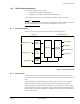
11.2.1 TPIU block diagrams
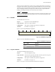
Figure 11-1 shows the component layout of the TPIU for both configurations.
Figure 11-1 TPIU block diagram
11.2.2 TPIU Formatter
The formatter inserts source ID signals into the data packet stream so that trace data can be
re-associated with its trace source. The formatter is always active when the Trace Port Mode is
active.
The formatting protocol is described in the CoreSight Architecture Specification. You must
enable synchronization packets in the DWT to provide synchronization for the formatter.
When the formatter is enabled, half-sync packets may be inserted if there is no data to output
after a frame has been started. Synchronization, caused by the distributed synchronization from
the DWT, will ensure that any partial frame is completed, and at least one full synchronization
packet will be generated.
ATB
Interface
Formatter
APB
Interface
Trace Out
(serializer)
ITM ATB Slave Port
APB Slave Port
TRACECLKIN
TRACECLK
TRACEDATA [3:0]
TRACESWO
CLK Domain
TRACECLKIN Domain
† ATB
Interface
† ETM ATB Slave Port
† Optional component