
User manual
1: Introduction
GP4020 GPS Baseband Processor Design Manual 1
1 INTRODUCTION
1.1 GP4020 GPS Baseband Processor Overview
This design manual describes the GP4020 GPS Baseband Processor, which is based on the Zarlink
Semiconductor Firefly MF1 Microcontroller Core (ref. Firefly MF1 Core Design Manual (DM5003)), and a custom
Navstar GPS C/A code 12-channel spread-spectrum correlator.
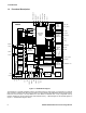
The GP4020 is a complete digital baseband processor for a Global Positioning System (GPS) receiver. It combines
the 12-channel correlator function of the GP2021 with an advanced ARM7TDMI
TM
(Thumb
) microprocessor to
achieve a higher level of integration, reduced system cost, reduced power consumption and added functionality.
The GP4020 complements the GP2015 and GP2010 C/A code RF down-converters available from Zarlink
Semiconductor.
The correlator section contains 12 identical tracking module blocks, one for each channel. Each channel contains
all the components necessary for acquiring and tracking the received signal, and contains other functional blocks,
which are used to produce part of the measurement data set. Individual channels may be deactivated for systems
not requiring full 12-channel operation and thus allowing for reduced power consumption and processor loading.
The microprocessor section contains the Firefly MF1 micro-controller core, which includes an ARM7TDMI with a
Thumb instruction de-compressor plus the Firefly BµILD module. Also included are a second UART, BµILD Serial
I/O, General I/O and WATCHDOG functions.
1.2 Features
• Complete GPS correlator and Firefly MF1 micro-controller core
• ARM7TDMI (Thumb) microprocessor, with JTAG ICEBreaker
TM
debug interface
• Fully configurable external data-bus
• 12 Fully Independent Correlation Channels
• Low Voltage operation; 3.3V
• Low Current Power–Down Mode
• 1PPS UTC Aligned Timing Output, with 25ns resolution
• System Clock Generator with Phase Locked Loop, capable of producing Flexible microprocessor clock speeds
• 32KHz Real Time Clock
• Dual UART
• 3-wire BµILD Serial Input / Output (BSIO) interface
• 8 General Purpose Input / Output (GPIO) lines
• Boot ROM, allowing software upload via UART
• 8k Bytes internal SRAM
• Compatible with GP2015 and GP2010 RF Front Ends