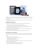
ARKBIRD is a high-accuracy autopilot designed for fixed-wing. It can superimpose OSD (On Screen Display) data on videos and at the same time control the balance, the return and many other maneuvers of your aircraft with high precision. The perfect auto-stabilization system and a plug-and-play design free you from worries and inconveniences and enjoy the beauty of FPV in an instant. Arkbird OSD 2.0 LITE Includes: 1.
10 Extended functions Meets all you need Launch Assist Run up with aircraft in hands, when the speed is higher than 5kmph, the throttle will start output and automatically control the take-off. Fence mode Out of rectangle area or safe height, it returns automatically, best helper for beginner Waypoint Mode It is able to trace the Way Point Set by menu. Hover mode Regard the hover position as balance position, nose up and keep steady Cruise flight Keep a straight & constant-height flight.
CONTENTS 1. Wirings 2. Power Supply Mode 3. 5V Dual Power Supply 4. Installation 5. Switch Modes through CH5 and CH6 6. GPS&Save Home Position 7. Manual Mode & Balance Mode 8. Fail-Safe to RTH mode 9. OSD and Menu 10. Balance Mode and RTH Adjustment11 11. FAQ and Solutions 12. Other FAQ 13.
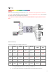
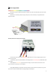
1Wirings Attention: Make sure connect according to the marked order of - + S. The black wire is the ground wire. It is close to the upper side. The signal wire below is for the yellow socket. Check all the wiring before power on. Don't mistaken 12v and 5v so as not to cause damage to the equipment. If your need to use RSSI function, please connect AIRSPEED METER on RX port, RSSI connect AR port. Mixed control output Arkbird 2.
3) If you are using AR port as RSSI, you can also connect Airspeed sensor to RX port. 4) Bi-motor mixed control, when throttle is less than 25%, there is no differential steering, when over 25%, throttle outputs differential steering. Attention: 1. If the camera needs a 5V supply, please connect a BEC from 12V or main power. Do not connect CPU 5V for a 5V camera in case of the power supply shortage. 2. Connect Receiver's CH1-7 to IN PORT or use a PPM connection.
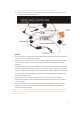
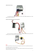
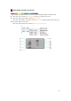
2 Power Supply Mode Recommend using one single 3S (12V) battery to supply motor power and Arkbird OSD, Video TX & camera (Shared supply), Otherwise, use one battery (4S-6S) to supply motor power, another 3S battery to supply OSD & Video (Separated supply). 3S Battery Shared Power Supply (Factory Default) Current sensor’s 3P wire wires in the motor power. Flight Power port is only for voltage display and have a maximum input of 33V. 1.
Independent Power Supply 2. If separated supply, remove the jumper, connect another 3S battery (800mah-1400mah) to the Video Power Port (12Vin) on the third row. Schematic drawing of Independent Power Supply Wiring (You can also choose the new Arkbird current sensor with 12V regulated output (accessories) which shares one battery with motor and the video sector.
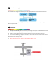
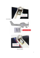
3 5V Dual Power Supply On broad OSD 12V to 5V regulator, with 5V BEC (form ESC) supplies power to the CPU module at the same time. If OSD function is not used, please plug in OSD 12V power as well to prevent a lack of power supply for 5V electronic speed controller. 4 Installation: 1. The pins of GPS and 12V ports shall stay forward (toward flying direction); the side with Arkbird LOGO shall be upward or vertical toward right wing. (Default is level installation) 2.
Vertical Installation 2 ways of installation -9-
5 Switch Modes through CH5 and CH6: After installation, test OSD and the radio control. Use CH5 and CH6 (0% to 100%) to switch flight mode. While CH5 < 50%, it switches to Manual Mode, autopilot is not involved in the control. While CH5 > 50% and CH6 < 30%, it switches to Balance Mode; While CH5 > 50% and 30% < CH6 < 70%, it switches to Custom Mode(Waypoint Mode ,Hover Mode, Fence Mode, RTH mode), Default is RTH mode. While CH5 > 50% and CH6> 70%, it switches to Return-to-home (RTH) Mode.
6 GPS & Save Home Position After power on, Arkbird will start to search GPS satellite and save the first valid position as Home. During searching, the elevator will be up and any manipulation of radio stick is invalid. If need to skip the searching, please push CH6 more than 75% and push CH1 to left or right side for 1 second. Once skipped the searching, it CANNOT switch to RTH mode, RTH logo will flash but it is balance mode. Attention 1.
7 Manual Mode & Balance Mode Radio Stick and SUB-TRIM back to center, set radio travel range as 100%. Switching to Manual Mode, Arkbird will not participate control, set manual control’s reverse through radio, adjust plane’s CG and travel angle, make sure plane can fly stably in horizontal without Autopilot.
If the compensation direction is not correct, please adjust the Yaw inverse in OSD menu -> Flight parameters. If using Mixed-control, check the compensations for a leveling flight, pay attention to differential steering speed if using Bi-motor control. 7 GPS and Return to Home Instruction While switching to RTH Mode (CH5 to 100% and CH6 to 100%), it will adjust the flying height to safe height to go home.
9 OSD and Menu CH5 switches to Manual Mode(<50%), throttle to 0%, and push CH1 to left or right side for 6 seconds, it will enter into main menu. Exit the main menu if CH5 switches to auto mode(>50%). Moving stick up and down to change the value, pushing to right side to select, and pushing to left side to exit and save parameters.
Set CTL Parameters Roll Ctl Roll Control(%)(equivalent to travel range on radio, Please adjust the travel range on OSD, do not adjust through radio) Pitch Ctl Pitch Control (%) Yaw Ctl Yaw Control (%) ------------------------------------------------------------------------------------------------------------ -----------------------------------Neutral Check Neutral Point Check: Neutral point alignment needed under first installation, not used for weeks, or temperature variation is more than 10 degree
Gyro : Gyro Mode, it will do compensation for unintentional attitude changes. Lock Dir/Heig: Lock direction and height (Cruise flight): Under balance mode, when CH3>20% CH1 and CH2 stick back to center, height and direction will be locked and keep straight &constant-height flight. Aileron and elevator can also be controlled through CH1 and CH2.
Set OSD Parameters Language Chinese/English Page switching Show Lat-long Show longitude and altitude AD Calibrate Battery voltage calibration OSD Pattern OSD interface selection Default: Normal interface Fighter:HUD interface P or N (Xin) PAL/ NTSC selection Show RSSI Display the AR port's voltage, 0-3.3V is corresponding to 0-100% Cur Man Calibrate Current calibration %. The current sensor will adjust and input the correct power.
Yaw Yaw Reverse MIX More ways of mixed control include delta wing and V-tail wing, and Bi-motor plane, Bi-motor flying wing and butterfly brake (mixed control of 1247channel).
advised to use a three section switch to control the flap wing so as to avoid accidence. When install the servos, please adjust the CH7 to make the “flap/brake value "on the OSD is 100% (zero point),then install a level rudder surface. As the design of the aircraft shape, some aircraft may nod when lower the flap. As most of the ailerons are on the outer side, when channel 1/7 mix control, the flap movement may cause the left and right side of the flight uneven.
Brake Ctl CH7 (default): CH7 controls the rudder amounts of brake. InnerBrake Max Inner Brake Max: It is the maximum position at the two control surfaces in inner side when it brakes (OSD displays F, 100% output brake quantity). When this item gets into the adjusting, the servos will output the adjusting value, Correct InnerBrake value can be set according to the rudder position.
Way Point Set Set four way points (WP1~WP4), allow to turn on/off separately. Set Custom Mode as Way Point Mode (CH5 > 50% and 30 %< CH6< 70%). The plane will fly in a loop upon the sequence of 1 to 4, skip the waypoint turned off, and return to home while over the safe time. WP safe time ---------WP safe time. Returning to home if reaches the safe time. Re-timing only next power-on.
WP3 ---------WP 3 On/Off Lng Dist --------- Waypoint 3 East-West distance away from Home (m) “>” means East and “<” means West Lat Dist ---------Waypoint 3 South-North distance away from Home (m) “︾”means South and “︽” means North Height WP4 ---------Waypoint 3 Height(m) ---------WP 4 On/Off Lng Dist --------- Waypoint 4 East-West distance away from Home (m) “>” means East and “<” means West Lat Dist ---------Waypoint 4 South-North distance away from Home (m) “︾”means South and “︽” means North H
Adjusting Balance Mode: Purpose: Stick and SUB-TRIM back to center, plane can be able to flight levelly. 1. Please increase control value (“ctl” in CTL menu) or plane’s control surface when the stability not good enough (drift even stick back to center), and decrease it when the plane swings. 2. If plane pitches up or down when stick back to center, please adjust the “elevate angle” value (Do not adjust through SUB-TRIM, otherwise RTH Mode won’t be precise.) Adjusting Return to Home Mode: 1.
11 FAQ and Solutions: ★When switching to Balance Mode, the elevator will lift up a bit because the “Elevate Angle in a level flight” in the menu is defaulted as 5°. Which means the plane will rise a bit in a level flight to ensure a level route. ★If the CH1 has touched the edge but you cannot enter the menu, please check if the route setup is too small on the remote control. ★It’s normal when the direction of compass and return arrow is inaccurate while testing on the ground.
13 Attentions: Please read through carefully: 1. The design purpose of autopilot is to keep balance of flight, it is not able to manipulate plane or prevent stall. You must have sufficient experiences of fixed wing to control the flight. 2. The autopilot is only for small-scale RC model. For safety concern, please do not install in plane for aerial photography which might fly over crowd. 3. Please install the autopilot depends on your demands and check the condition before flying every time. 4.