
Technical data

8
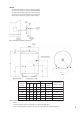
Table 3: Sizing of copper discharge pipe (D2) for common temperature relief valve outlet sizes
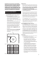
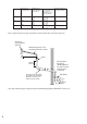
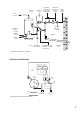
Fig. 5: Typical discharge pipe arrangement (extract from Building Regulation G3 Guidance section 3.9)
VALVE OUTLET
SIZE
MINIMUM SIZE OF
DISCHARGE PIPE D1
MINIMUM SIZE OF
DISCHARGE PIPE D2
FROM TUNDISH
MAXIMUM RESISTANCE
ALLOWED, EXPRESSED
AS A LENGTH OF
STRAIGHT PIPE (I.E. NO
ELBOWS OR BENDS
RESISTANCE CREATED BY
EACH ELBOW OR BEND
G 1/2 15MM 22mm
28mm
35mm
UP TO 9M
UP TO 18M
UP TO 27M
0.8M
1.0M
1.4M
G 3/4 22MM 28mm
35mm
42mm
UP TO 9M
UP TO 18M
UP TO 27M
1.0M
1.4M
1.7M
G 1 28MM 35mm
42mm
54mm
UP TO 9M
UP TO 18M
UP TO 27M
1.4M
1.7M
2.3M
Fixed grating
Discharge below
fixed grating
(Building Regulation
G3 section 3.9d gives
alternative points
of discharge)
Trapped
gully
Discharge pipe (D2) from tundish,
with continuous fall. See Building
Regulation G3 section 3.9d i-iv,
Table 4 and worked example
300mm
minimum
500mm maximum
Metal discharge pipe (D1) from
Temperature relief valve to tundish
Tundish
Safety device
(e.g. Temperature
relief valve)