
Technical data

16
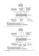
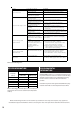
Table 5: Fault fi nding chart
Table 6: Standing heat losses (based on an ambient air
temperature of 20
o
C and a stored water temperature
of 65
o
C)
OTHER INFORMATION
ENVIRONMENTAL
INFORMATION
CENTERSTORE products are manufactured from many
recyclable materials. At the end of their useful life they
should be disposed of at a Local Authority Recycling
Centre in order to realise the full environmental
benefi ts.
Insulation is by means of an approved CFC/HCFC free poly-
urethane foam with an ozone depletion factor of zero.
YDEMERESUAC ELBISSOPTLUAF
1. Mains supply o.
2. Strainer blocked.
and clean (see Maintenance section).
3. Cold W ater Combination
V alve incorrectly tted.
3. Check and ret as required.
1. BACK UP immersion heater
not switched on.
1. Check and switch on.
2. BACK UP immersion heater
therm al cut-out has operated.
2. Check. Reset by pushing button.
3. INDIRECT programmer set
to Central Heating only.
3. Check. Set to a Dom estic Hot W ater
progr
amme.
4. INDIRECT boiler not
working.
4. Check boiler operation. If fault is
suspected consult boiler manufacturer's
ins tructions.
5. INDIRECT thermal cut-out
has operated.
5. Check. Reset by pushing button on cut-
out. Check operation of indirect thermostat.
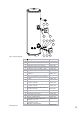
6. INDIRECT motorised valve
not connected correctly.
6. Check wiring and/or plumbing
connections to motorised valve (see Fig. 7).
1. INTERMITTENTLY
Expansion Vessel charge
pre
ssure has reduced below
3.5bar.
1. See Maintenance section for re-charging
procedure.
2. CONTINUALLY
a. Cold W ater Com bination
Valve Pressure Reducer not
working correctly.
2a. Check pressure from Cold W ater
Com bination Valve. If greater than 3.5bar
replace Pressure Reducer cartridge.
b. Expansion Valve seat
damaged.
2b. Remove Expansion Valve cartridge.
Check condition of seat. If necessary t
new Expansion Valve cartridge.
W ater discharges from
T&P Relief Valve
1. Thermal control failure
NOTE water will be very hot.
1. S witc h o power to im m ers ion heater(s )
and shut down boiler. DO NOT turn o
water supply. When discharge stops
check all thermal controls, replace if faulty.
Milky water
1. Oxygenated water.
releases oxygen bubbles when owing. The
milkiness will disappear after a short while.
No hot water ow
W ater from hot taps is cold
W ater discha
rges from
Expansion Valve
1. Check and open stop cock.
2. Turn o water supply. Rem ove strainer
1. W ater from a pressurised system
per day
(kW h/24h)
per year
(kWh/365d)
120 1.47 537
150 1.70 621
170 1.92 701
210 2.10 767
Standing Heat Loss
Nominal
Capacity
(litres)
250 2.22
300 2.52
811
920
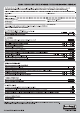
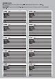
While the following Checklist can be used for any installation covered by its description, only appliances
manufactured by Scheme Members will be covered by the rules and requirements of the Benchmark Scheme.