
Operation Manual

Heat pump water heater – GENERAL INFORMATION
30
2.2
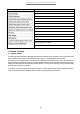
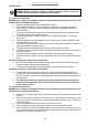
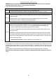
Internal unit
construction features
fig. 1-2.
FIG.1
MODEL
150
LITRES
MODEL
20
0
LITRES
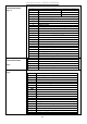
A
725
1050
B
500
800
C
1150
1476
D
Outlet hot water 3/4” pipe
E
Inlet cold water 3/4” pipe
F
Outlet gas pipe
3/8 “
G Inlet gas pipe 1/4 “
H
Battery housing
I
Housing electrical connections and heating element
L
Interface board
M
Condenser
N Wall brackets
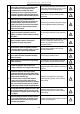
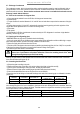
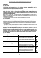
FIG.2 MODEL 300 LITRES
O
Battery housing
P
Interface board
Q
Condenser
R
Inlet cold water 3/4” pi
pe
S
heating element
housing
T
feets with adjustable height
U
Inlet gas pipe 1/4 “
V Outlet gas pipe 3/8 “
Z
E
lectrical connections
h
ousing
Y
Outlet hot water 3/4” pipe
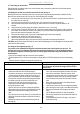
2.3
External unit
construction features
fig. 3.
A
Fan
B
E
lectrical connecti
ons
h
ousing
C
Gas connections
D
Gas connections housing cover
E
Hole for condensation drain
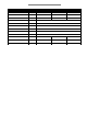
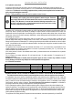
2.4
Electrical diagram
fig. 4.
SYMBOL
DESCRI
PTION
A
Power supply,
cable not supplied with the product
B
Batterie
s
C
Interface board
D
Heating element
E
NTC sensor for heating element zone
F
Impressed current anode
Earth connection
H
Serial connection board
I
M
ainboard
L
Operation condenser
M
Compressor
N
Fan
O
Defrost four way valve
P
Safety pressure switch
Q
NTC sensor for hot water pipe zo
ne
R
NTC sensor for evaporator and inlet air
S
Probe connection cable
,
supplied with the product
T
Electronic filter
EDF
HCHP signal (EDP)
–
cable not supplied with the product