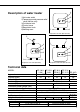
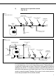
Unvented water heater
4 Description of water heater 1)Hot water outlet 2)Temperature and pressure relief valve (30 litre only) 3)Cold water inlet 4)Control cover 5)Regulation knob 6)Heating neon 5 6 1 3 Europrisma over-sink (EP 10/15 O) 2 3 4 1 4 5 5 6 6 1 3 Europrisma over-sink (EP 30 O) Europrisma under-sink (EP 10/15 U) Technical data MODEL Approval Capacity (litres) Current (A) Tension (V~) Power (W) Immersion Heater Length (mm) Immersion Heater Type Immersion Heater Refernce Number Pressure max.
User instructions PLEASE KEEP THIS BOOKLET FOR FUTURE REFERENCE The heater is insulated to a high standard therefore it may be left on all the time. The temperature of the water may be adjusted by turning the knob on the front of the heater, allow half an hour for the temperature to stabilise between settings. Maximum temperature is achieved with the knob turned fully clockwise. The <> mark on the regulation knob indicates an <> setting and corresponds to a water temperature of 55 - 60°C.
How the heater works The heating element is controlled by a thermostat which senses the water temperature. The operating temperature can be adjusted by the regulation knob on the front of the heater. In addition to the thermostat there is a thermal cut-out which is set to switch off the power to the element if the thermostat fails and the water temperature rises too high. Once the cut-out operates it can only be reset manually (this should be carried out by the installer - see maintenance).
Access to the heater is not normally needed on a day-to-day basis, but 300mm clearance to the front of the water heater sould be kept for servicing and maintenance A cold water supply pressure between 1 and 5.5 bar is required (if the mains pressure is above 5.5 bar a pressure reducing valve will need to be installed). Please note that turning down the stop-cock will reduce flow not pressure. The outlet pressure from the reducing valve (if supplied) is 3.5 bar.
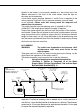
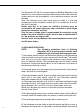
2) Using a set of expansion controls (Fig. 2 & 3). Fig.. 2 Europrisma EP 10/15 Expansion vessel (charge at set 3.5 bar) Nearest cold water Pressure relief valve draw-off (6 bar) Hot Dielectric junctions Pressure reducing valve (set at 3.5 bar) Isolating valve (fixed jumper or 1/4 turn ball type) Cold Cold water mains Non-return valve Supply to other parts of plumbing system Discharge Fig.
The Europrisma EP 30 O is covered under the Building Regulations and therefore it is not possible to accommodate the expansion water within the system pipe work and consequently a set of expansion controls must be installed. Note: The discharge from relief valves must be made in a safe and conspicuous manner; therefore a tundish (Kit C) is available for 10 and 15 litre units if required.
be clear visibility at one or other of these locations. Examples of acceptance are: i) Ideally below a fixed grating and above the water seal in a trapped gully. ii) Downward discharges at a low level; i.e. up to 100 mm above external surfaces such as car parks, hard standings, grassed areas etc. These are acceptable providing that where children may play or otherwise come into contact with discharges, a wire cage or similar guard is positioned to prevent contact, whilst maintaining visibility.
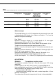
Table 2 Sizing of copper discharge pipe “D2” for common temperature valve outlets. Valve outlet size Minimum size of discharge pipe D1* Minimum size of discharge pipe D2* from tundish Maximum resistance allowed, expressed as a length of pipe (i.e. no elbow or bends) Resistance created by each elbow or bend G 1/2 15 mm G 3/4 22 mm G1 28 mm 22 mm 28 mm 35 mm 28 mm 35 mm 42 mm 35 mm 42 mm 54 mm Up to 9 m Up to 18 m Up to 27 m Up to 9 m Up to 18 m Up to 27 m Up to 9 m Up to 18 m Up to 27 m 0.8 m 1.
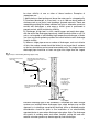
the foam insulation, the entrance to this tube is on the right hand side at the bottom. Flexible cables are colour coded as follows: Brown.................................................. live Blue............................................... neutral Green and yellow............................. earth THERMAL CUT-OUT THERMOSTAT HEATING ELEMENT NEON L N E Fig..5 EP 30 O wiring diagram THERMAL CUT-OUT THERMOSTAT BIPOLAR SWITCH L HEATING ELEMENT L1 NEON N L2 E Fig..
e) COMMISSIONING - Check that all the necessary components are supplied and for those not factory fitted, that they are the type recommended by the manufacturer for the particular water heater. - Check that the water heater/components are undamaged. - Check that the discharge pipe is plumbed so that it falls continuously and that no taps, valves or other shut-off devices are installed in the pipe. - Check that the discharge pipe drains safely to waste and is readily visible.
i) for under-sink models (EP 10 U - EP 15 U) disconnect pipes and removed the heater from the wall. ii) for over-sink models (EP 10 O - EP 15 O - EP 30 O) undo the cold water supply pipe and open a hot water tap. The heating element may be removed (after taking out the thermostat phials on model EP 30 O) by undoing the M6 nut. The assembly should then be turned through 90° anti-clockwise to ease removal from the water container.
3)Dripping while unit heating. Cause: Not enough pipe work for expansion; or stop-cock, non-return valve or pressure reducing valve has been fitted within the distance required for expansion (see page 5, Fig.3). If an expansion vessel has been fitted, the charge may have failed. 4)No hot water. Cause: Thermal cut-out has operated. The heating element has burnt-out. The thermostat is faulty. 5)Milky water. Cause: This is a result of heavily limed and oxygenated water being heated.
Accessories Kit A (expansion vessel (2 l) and non-return valve) Kit B (pressure reducing valve 3.
MTS MAKES USE OF RECYCLED PAPER Manufactured by: Commercial subsidiary: Merloni TermoSanitari SpA MTS (GB) LIMITED Viale Aristide Merloni, 45 60044 Fabriano (AN) Italy Tel. + 39 0732 6011 Telefax. + 39 0732 602331 Telex 560160 http://www.mtsgroup.com MTS Building Hughenden Avenue High Wycombe Bucks HP13 5FT Telephone: (01494) 755600 Fax: (01494) 459775 Internet: http://www.mtsgb.ltd.uk E-mail: info@mtsgb.ltd.