
Installation manual


Supplied By www.heating spares.co Tel. 0161 620 6677
1.
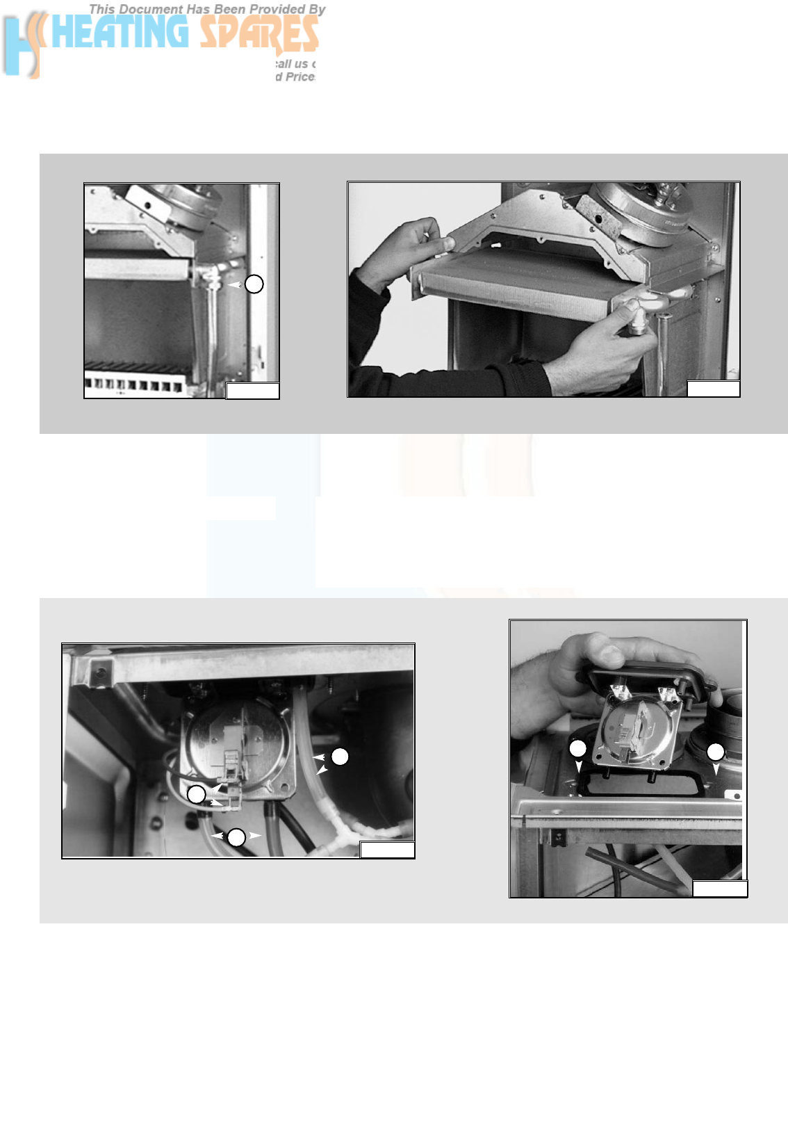
Disconnect the electrical connections “K” and silicone pipes “L” from their
connection points
(see fig. 1.18)
;
2.
Remove screws “J” on the top of the sealed chamber
(see fig. 1.19)
;
Use a No. 2 star tip screwdriver to remove the switch from the plate.
Fig. 1.19
Fig. 1.18
7
B005
1.
Drain the boiler of water;
2.
Release the two connection nuts “I” connecting the exchanger to the flow
and return pipes
(see fig. 1.16)
;
3.
Pull it straight out
(see fig. 1.17).
Removing the main heat
exchanger
Removing the air pressure switch
Fig. 1.16
I
Fig. 1.17
L
L
K
J
J