Operating Instructions HOB Contents GB Installation, 2-5 GB English,1 RS ,12 Positioning Electrical connection Gas connection Data plate Burner and nozzle specifications Description of the appliance, 6 Overall view Start-up and use, 7-8 Practical advice on using the burners Practical advice on using the electric hotplates Precautions and tips, 9 CISPH640 M /HA CISPH640 M IX /HA CISPH640 MS /HA CISPH640 MS IX /HA CISPH640 MST /HA CISPH640 MST IX /HA 7HPH 640 RU/HA 7HPH 640 GH RU/HA 7HPH 640S RU
Installation ! Before operating your new appliance please read this instruction booklet carefully. It contains important information for safe use, installation and care of the appliance. also be equipped with vents to allow gas to escape in the event of a leak. As a result LPG cylinders, whether partially or completely full, must not be installed or stored in rooms or storage areas that are below ground level (cellars, etc.).
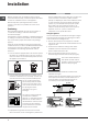
Front Hooking position for top H=40 mm Connecting the supply cable to the mains Back ! Use the hooks contained in the “accessory pack” • Where the hob is not installed over a built-in oven, a wooden panel must be installed as insulation. This must be placed at a minimum distance of 20 mm from the lower part of the hob. Ventilation To ensure adequate ventilation, the back panel of the cabinet must be removed.
GB appliance supply ramp and this is fitted with a seal in order to prevent leaks. The seal must always be replaced after rotating the pipe fitting (seal provided with appliance). The gas supply pipe fitting is a threaded 1/2 gas cylindrical male attachment. Connecting a flexible jointless stainless steel pipe to a threaded attachment The gas supply pipe fitting is a threaded 1/2 gas cylindrical male attachment. These pipes must be installed so that they are never longer than 2000 mm when fully extended.
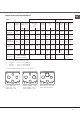
Burner and nozzle specifications GB Table 1 Liquid Gas Burner By-pass 1/100 (mm) Diameter Thermal Power (mm) kW (p.c.s.*) Nom. Red. Natural Gas Nozzle 1/100 Nozzle Flow* Nozzle Flow* l/h 1/100 l/h 1/100 Flow* g/h (1) (mm) *** ** (mm) (mm) Fast (Large) (R) 100 3.00 0.70 41 39 86 218 214 116 286 143 286 Reduce Fast (RR) 100 2.60 0.70 41 39 80 189 186 110 248 135 248 Semi Fast (Medium) (S) 75 1.65 0.
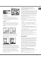
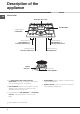
Description of the appliance GB Overall view ELECTRIC HOTPLATE * GAS BURNERS Support Grid for COOKWARE 1 6 2 5 4 Control Knobs for GAS BURNERS and ELECTRIC HOTPLATES * Indicator Light for ELECTRIC HOTPLATE * SAFETY DEVICES * • The INDICATOR LIGHT FOR ELECTRIC HOTPLATES* switches on whenever the selector knob is moved from the ‘off’ position. • GAS BURNERS differ in size and power. Use the diameter of the cookware to choose the most appropriate burner to cook with.
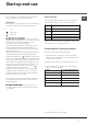
Start-up and use ! The position of the corresponding gas burner or electric hotplate* is shown on every knob.
GB Practical advice on using the electric hotplates To avoid heat loss and damage to the hotplates, use pans with a flat base, whose diameter is no less than that of the hotplate itself. Setting Setting 0 Off 1 Cooking vegetables, fish 2 Cooking patatoes (using steam) soups, chickpeas, beans. 3 Continuing the cooking of large quantities of food, minestrone.
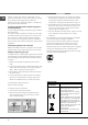
Precautions and tips ! This appliance has been designed and manufactured in compliance with international safety standards. The following warnings are provided for safety reasons and must be read carefully. General safety • This is a class 3 built-in appliance. • Gas appliances require regular air exchange to maintain efficient operation. When installing the hob, follow the instructions provided in the paragraph on “Positioning” the appliance.
Maintenance and care GB Switching the appliance off Gas tap maintenance Disconnect your appliance from the electricity supply before carrying out any work on it. Over time, the taps may become jammed or difficult to turn. If this happens, the tap must be replaced. Cleaning the appliance ! This procedure must be performed by a qualified technician authorised by the manufacturer.
Troubleshooting It may happen that the appliance does not function properly or at all. Before calling the service centre for assistance, check if anything can be done. First, check to see that there are no interruptions in the gas and electrical supplies, and, in particular, that the gas valves for the mains are open. GB Problem Possible causes/Solution The burner does not light or the flame is not even around the burner. • The gas holes on the burner are clogged.
RS GB RS
Непосредственно в атмосферу A Примеры вентиляционных отверстий для притока воздуха для горения
RS
RS Таблица 1 Kонфорка Диаметр (мм) Теплотворная способность кВт (p.c.s.*) Быстрая (сокращенная) (RR) Полубыстрая (Средняя)(S) Вспомогательная (Малая) (А) Тройная (ТС) Форсунка 1/100 Форсунка Расход* Форсунка Расход* 1/100 л/час 1/100 л/час Расход* г/час (1) (mm) *** ** (mm) 3.00 0.70 41 39 86 218 214 116 286 143 286 100 2.60 0.70 41 39 80 189 186 110 248 135 248 75 1.65 0.40 30 28 64 120 118 96 157 105 157 55 1.00 0.
RS 1 6 2 5 4 g=?,2…% 3“2!%L“2"% * 3 q" = ƒ=›, =…, =ƒ%"/L *%…-%!%* *
RS
!
RS !
RS
RS
RS 23
06/2010 - 195061733.